- Joined
- Jan 1, 2000
- Messages
- 16,233
- Reaction score
- 4,202
- Points
- 113
- Age
- 81
- My Satellite Setup
-
Triple Dragon, Dreambox 8000, Echostar AD3000ip, TBS6522,6925,6983 PCie cards.
Gibertini 1.25m motorised dish driven by the AD3000, with either Inverto BU Quad or Norsat / XMW Ka LNBs . SMW 1.05m + 3 other dishes. Speccy: Promax HD Ranger+
- My Location
- The Flatlands of East Anglia
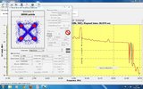
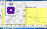
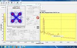
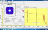
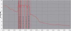
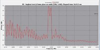
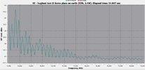
The 19E scans with the 27MHz setup in line. Two without the H/V ports switched (Horizontal port active) - 27MHz switch off. Other two with switch on (Vertical port active).
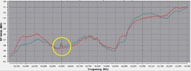
So I presume these are circular feeds? - both show before and after switching.
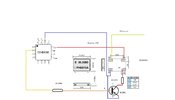
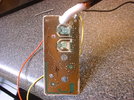
Having the switch assembly inserted between the LNB and receiver (pci card -> Crazyscan) seems to increase the noise floor when the 27MHz signal is switched on. I think maybe it's too strong a signal and the receiver (my pc card) can't filter it out sufficiently. No doubt the receiver that's normally used with the Hughes setup has efficient filtering. Will need to look into adding a HPF between the switch and card.
So I presume these are circular feeds? - both show before and after switching.
Having the switch assembly inserted between the LNB and receiver (pci card -> Crazyscan) seems to increase the noise floor when the 27MHz signal is switched on. I think maybe it's too strong a signal and the receiver (my pc card) can't filter it out sufficiently. No doubt the receiver that's normally used with the Hughes setup has efficient filtering. Will need to look into adding a HPF between the switch and card.