Anyone tried to make BIG dish at home?

It would work, with careful cutting of the reflector edges to ensure the parabolas do not distort from the pressed form.

The main problems I can see would be
1)the supporting of all the reflectors, (which would almost certainly add cost to the point it might be worth buying a 1.8m in the first place),
2) Finding a feed that is matched to the new design, now prime focus, of an f/d ratio that is most likely unlike anthing on the market, and
3) Fabricating a mount that can connect to the new backplate(s) that doesn't distort what you have achieved.
 
Hi Channel Hopper

There is a very fine line between "hobby" and "mental illness"

I like this blog and like diskuss about maybe not to practical thinks. Who can tell me where is the fine line exactly?

You are right it is not too usable but I think diskuss is if it is possible or not. On the end it could direct to something other better.

To fta-elite:
thank you for pictures it looks very parabolic :-)
 
JanH said:
There is a very fine line between "hobby" and "mental illness"

I like this blog and like diskuss about maybe not to practical thinks. Who can tell me where is the fine line exactly?

If you don't know then you have probably crossed it.
 
Channel Hopper said:
If you don't know then you have probably crossed it.


Been there and back again CH ..
Damned if I know where to get the 'T'shirt
;)
 
Who needs one when you have the tattoo
 
Channel Hopper said:
If you don't know then you have probably crossed it.

Ok but I am happy with it -:)

I spend some time to resolve my own problem if possible to "connect" together more dishes. I thing it may possible but losses will be big and solution effeciency will be bad. There is problems with system mechanic stability, active dishes surface going down and additional reflectors make losses too. One big dish is easy sureness.
 
JanH said:
Ok but I am happy with it -:)

I spend some time to resolve my own problem if possible to "connect" together more dishes...


The first problem you must solve first it s the signal lost in the waveguide lenght.Ku band perform very bad inside the tubes.Year s ago i make one simple test using half meter aluminium pipes,it s was enough to all Ku-band signal to be lost.
I have today more 90 degree curves make from square aluminium pipes and other stuff ready to be welded and tested.
After my opinion, the only viabile solution it s to replace the tubes with the optical gadget.The Ku-band work well only in the air,except profesional stuff,the calculation about waveguide it s beyound enthusiast like us.Few exception,i hope.
Maybee you know,guys,what have inside the profesional 90 degree curves working on Ku band.One small mirror ? Or nothing ?
I have one picture with 90 degree curves.It s impotrant to know becose each dish of the sistem need two 90 degree curves and one segment long enough to coverage the distance from the dish to the central point where the LNC it s located.The sistem looks like one flower,petalised not with panels but by parabolic dishes.
 

Attachments

  • 90 degree curves.webp
    90 degree curves.webp
    104.7 KB · Views: 136
Sorry, I am not good enough to fully follow.

What do you mean "90 degree curves".
What about "replace the tubes with the optical gadget". Sounds good but I do not know about the idea.

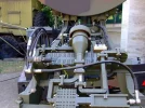
Nice military equipment :-)
I can recognize LNB, Band filter, In/Out mixer and huge feedhorn connected together with waveguides as well as offset antenna.
 
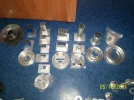
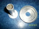
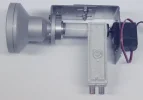
Mr. JanH watch the picture,they are about C-Ku band feedhorn,manufactured at home by myself.Optical gadget means mirror.Small mirror.That military equipment have few 90 degree curves inside the equipment.Inside the curves,microvawe frecvency flow from one part of equipment to another with minimum loss of signal.
One large Ku-band dish it s expensive,all people know that,i think it s time to collect the signal from few parabolic dishes in one Ku band array. in this case You need pipes from each dish focal point to one single central focal point where LNC it s located.To do that the Ku band signal need curves,90 degree in this case,each parabolic dish need two 90 degree curves.
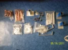
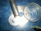
I make at home one simple test using 45 degree curves-(see the picture about cooling) and i found the signal lost after Ku band signal turn 45 degree.
Making this test it s more easy to handle 4 offset 0,6m and collect the signal in the central point using pipes and curves.

I found samthing intrestind on internet few days ago,when i want to watch again one video,it s talking about„cooling lnb to improve reception”. If this video it s a crap why somebody spent time to delay the video,and more,Mr Schumaker in Brasil using 8m dish it s missing from internet.Somebody delay the video.
Unfortunately i have problem here in the East to found R 1150 refrigerant for deep freze application.This refrigerant work to -80C and if the refrigeration units work on two stages the temperature go well under -100C.
So,for now my limitation it s to -50C.When the refrigeration units it s complete i make the test.Cooling LNC-fact or fiction.


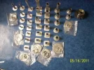
I have samthing for Mr. Satcom,Thank You for your useful C band offset cone scalar feed diagram.I make one at home,for C band.

I really need Yours help Guys,i need UHF Swan antenna diagram for frecvency above 600 MHz.And diagram about helix UHF antenna.I found on internet only for VHF band.
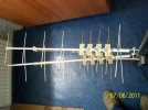
In the picture You found my homemade Swan antenna for Channel 21 and 41 UHF.Perform great this little toys.

Thank You for your time,
mouse.
 

Attachments

  • C BAND JPG.webp
    C BAND JPG.webp
    351.7 KB · Views: 96
  • Copper pipes in the left it s for cooling LNB project.In the center it s 45 degree curves..webp
    Copper pipes in the left it s for cooling LNB project.In the center it s 45 degree curves..webp
    301.8 KB · Views: 81
  • DE 13.webp
    DE 13.webp
    254.9 KB · Views: 89
  • KU BAND JPG.webp
    KU BAND JPG.webp
    329.4 KB · Views: 89
  • DE 14.webp
    DE 14.webp
    249.5 KB · Views: 82
  • suport-swan.webp
    suport-swan.webp
    355.3 KB · Views: 83
LNB freeze should work but I am not shure if LNB crashed or not and how big difference you will found because noise of input components is one part of noise only. Amplifiers could not work, there is materials different dilatation which destroy board etc. I think should be possible to warm up LNB a bit. You may see if C/N on receiver change notably or not. Looks more easy and result could by similar but oposit.
About dishes array. You mean to use feedhorn for each dish an each polarization and collect it separately by pipes to one point with LNB?
 
JanH said:
About dishes array. You mean to use feedhorn for each dish an each polarization and collect it separately by pipes to one point with LNB?

Yes,you undestand now.Signal from 4 dishes in one focal point.
 
I can imagine feedhorn in focal point of each array antenna connected by round pipe with equal size and lenght to one LNB. What about central focal point solution or LNB connection to four pipes? Or squared pipes for separate polarizations - 8 pipes? It is not so easy to me to imagine. How to design?
 
Sorry Mr.JahH,i m not talking about 8 pipes...,4 parabolic dishes,4 pipes to connect each antenna focal point to a single LNC in the middle of the parabolic array.The array it s made from multiple dishes,it s not mandatory to have only 4 parabolic dishes,5,6,7,8,9,10...,like flower petals.
Abot multiple polarisation the C-Ku corotor perform bad,have no application for fringe,so, go motorised to switch the band and polarisation,even skew fine adjustment.

My locatoin it s very bad about Astra 2 D,3m diameter it s not enough.200 Km away from my location 1,5m perform well few hours on day time.Here 5m dish it s the limits to start reception.5m expensive dish or array+cooling LNB it s the last hope.
The problem it s not to buid the array,this it s the easy part of the problem,it s the signal loss in the pipes and 2x45 degree curves.
Do You undestand now what i want exactly ?
 

Attachments

  • Ku band RA 3.webp
    Ku band RA 3.webp
    19 KB · Views: 69
  • C-Ku selector.webp
    C-Ku selector.webp
    146.4 KB · Views: 71
Oh
5m dish is really as fantasy for me. It is about BBC receving?
I tried it with 1.5m dish in the midle of Czech and nothink, no signal found.

For me is dark the LNB end of pipes. Signal must be merge to one pipe with LNB. There is big impedance and phase problem. I do not know how to. On your military picture is something similar but using square pipes and it is probably IN/OUT shunt.
I am pessimistic if it is realisable solution without measure equipments and deep knowledge.
You want to work up with very small signals and small mistake make it totally unusable.

On the other hand, BBC is not best of all. :)
English speaking programs are the problem, I think. Same for me.
JH
 
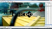
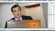
BBC One have the strong signal of all,but after 22 o clock dissapear from the screen.Here are few photos about 2 D reception in my country central area.This guy make extreme fine dish adjustment using one Strong 4500 receiver.Like satfinder perform excelent this receiver.The software it s from year 2006,Vulcan-Yumatu,it s the best for dish adjustment from all SD receiver.I have that software on my database,if You want.

In my location in s nothing,200 km away in Bucharest 3m i ts on the edge of reception,200 Km Vest in Cluj 1,5m it s enough for few hours reception,from 16 to 22 o clock.After this hour the signal shut down dramaticaly.
Try with cooling spray,and see the results.After LNB go down to -50C make the scan.Maybee works.If the cooling spray are not available ask a refrigeration engineer to give You few Kg of R 404a.It s the same like cooling spray,-50C.

Square pipes,round pipes,i must test all possibilities.
Germany it s not farr away from Your s location,maybee You found there one large old dish from analogic age, 3,7m Katherein for example,they perform excelent.Genuine dish like no other.
 

Attachments

  • 2 D -1.webp
    2 D -1.webp
    57.2 KB · Views: 103
  • 2 D-3.webp
    2 D-3.webp
    43.4 KB · Views: 62
  • 2 D-4.webp
    2 D-4.webp
    21.6 KB · Views: 58
  • 2 D-5.webp
    2 D-5.webp
    40.8 KB · Views: 70
  • 2 D-6.webp
    2 D-6.webp
    42 KB · Views: 51
  • 2 D-7.webp
    2 D-7.webp
    31.9 KB · Views: 70
  • 2 D-8.webp
    2 D-8.webp
    33.9 KB · Views: 64
  • 2 D-9.webp
    2 D-9.webp
    41.2 KB · Views: 68
  • 2 D-10.webp
    2 D-10.webp
    23.9 KB · Views: 59
Ok, I check to freeze some LNB with ordinary cooling spray, I have one. I will test it next weekend on normal good signal. I should see some change too.It is interesting that signal strongly depend on day time. I did not heard about it. Of course noise from sun could be different. But why this time?
JH
 
It's more than likely the transmit system has an automatic level control, so if solar noise is high (during the day) or if there is rain fade - the transmit signal will increase. At night the transmit signal will decrease (in order to maintain the same signal to noise in the designated catchment area). What this means is that the signal level drops below threshold in fringe areas. By having an ALC the lifespan of the satellite will be increased.
 
JanH said:
Make this simple test,it s more easy,covered half of the LNC with one metal plate with scotch,one coin for example,the signal it s blocked from that part of the dish,and only pixelation are available from that satelite signal.In the same time watch the tv screen to see the results.
Remove first the plastic coverage from the LNC in one part,the pipes cooling spray must touch the metal for a good cooling procedure,the cooling spray not last for longer in this summer days.
Above -34C nothing happens.If the cooling spray it s full,You have only few seconds to see the results.
 
I see.
I can check S/N information on recever or block some signal. I think dependance between input noise and temperature should be linear. No reason to be with some hop. Other matter is that LNB electronic can do something, for example change gain.

We need some friend on ASTRA team to gain signal a bit :)
 
Back
Top