Channel Master 1.8 Restoration

s-band

Specialist Contributor
Joined
Feb 7, 2016
Messages
1,186
Reaction score
1,843
Points
113
My Satellite Setup
1.5m IRTE PF, Octagon OSLO external Ref., TBS6983,
Various L, S, C, X & Ka bits. 1.2m S/X/Ku/Ka Prodelin on Az-El (being refurbished)
My Location
Essex
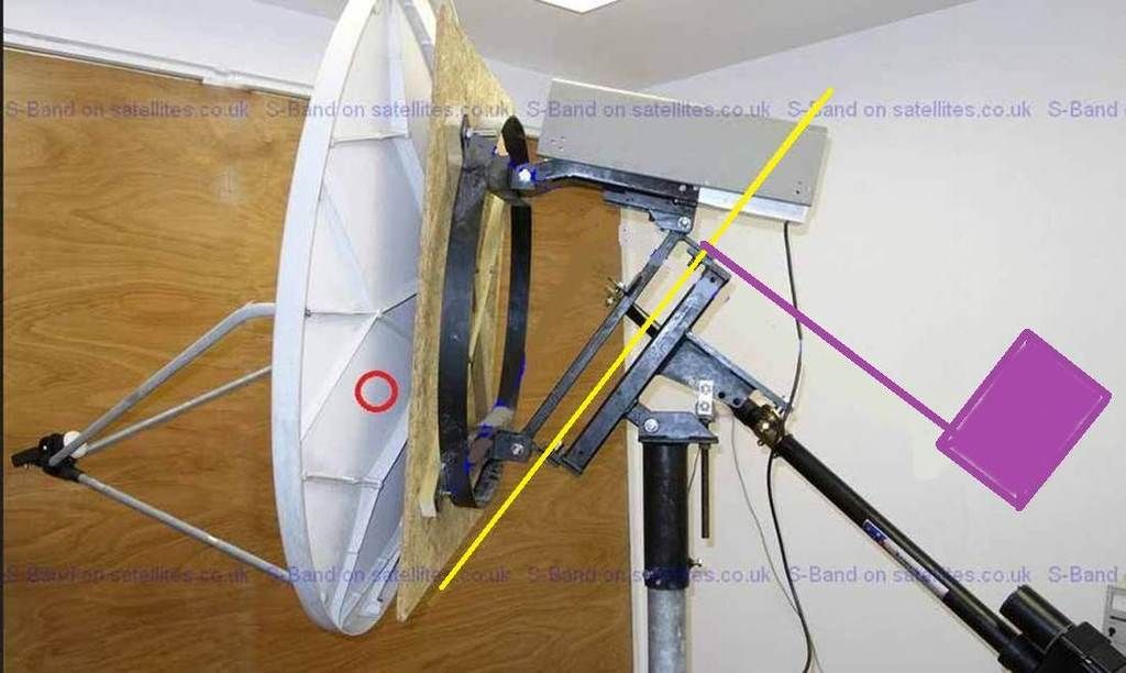
The actuator drives the 1.2 OK but at its limit even the 1.2 is not easy to shift manually. The only flop is caused by the fixed joint slop mentioned above, the moving mount isn't too bad. I've only ever used big PF dishes in the past and hadn't quite realised how out of balance the offset is - obvious if I'd thought about it more. Even the old 3m was easier to handle than this thing. The inclined drive is fine and very smooth, the vertical load is taken by the mount. The current drawn by the Linak is quite low indicating it's not straining too much. Looking at the mount and it's full range of movement, the pic below is the only way I can see to add a counterbalance easily. In plan view it will be an H frame with 2 weights. However, it's going to increase the dead weight by 50kg, at a guess, although that will be vertical if balanced. Does this make sense?
ScreenHunter_294 Apr. 23 00.05 copy.jpg

I did a quick test using a Sharp PLL BS1K2EL LNBF. It took about a minute to align to 1W (benefit of inclined tracking). I compared it to the 1.5PF (Inverto black) and the results suggest that the PF is not aligned. Using 30W, the average SNRs were:

Code:
     1.5PF       1.2CM
H     14.2         14.4
V     14.2         13.9
Tps   71           73

The detail suggests that the PF feed or LNB falls off a bit at the bottom end. It is quite likely that the PF is mis-aligned as it has not been tweaked for >10 years. EBSPro files attached.

Another observation was that the cross polar rejection was only 16-18dB on the CM but is 20-24 on the PF. Also, the position of the feed on the CM holder did not seem very critical. The sharp has a long neck and moving it 25mm only made fractions of a dB difference. There are too many variables in this comparison but it was done mainly to play with the mount.
 

Attachments

  • 1.2_vs_1.5.zip
    4.9 KB · Views: 12
Last edited:

moonbase

Small Dish Man
Joined
Mar 29, 2004
Messages
4,370
Reaction score
4,470
Points
113
My Satellite Setup
.
My Location
UK
...The inclined drive is fine and very smooth, the vertical load is taken by the mount. The current drawn by the Linak is quite low indicating it's not straining too much...


The 8" LINAK actuators seem to be high quality and useful for inclined orbit tracking. :)


Rgds
 
Last edited:

moonbase

Small Dish Man
Joined
Mar 29, 2004
Messages
4,370
Reaction score
4,470
Points
113
My Satellite Setup
.
My Location
UK
@s-band

If you decide to look into the option of a Venture actuator for azimuth movement of your Channel Master 1.8m dish I may still have the email with prices I was quoted to import some from the USA. The shipping price should reduce per unit the more units purchased should there be enough interest in a mini group buy?

Rgds
 

s-band

Specialist Contributor
Joined
Feb 7, 2016
Messages
1,186
Reaction score
1,843
Points
113
My Satellite Setup
1.5m IRTE PF, Octagon OSLO external Ref., TBS6983,
Various L, S, C, X & Ka bits. 1.2m S/X/Ku/Ka Prodelin on Az-El (being refurbished)
My Location
Essex
@RimaNTSS I have the parts to add the counterbalance now. Do you think it should be set up like this:

ScreenHunter_294 Apr. 23 00.05 copy.jpg

or like this (lower c of g)?:

ScreenHunter_294 Apr. 23 00.05_3.jpg
 

moonbase

Small Dish Man
Joined
Mar 29, 2004
Messages
4,370
Reaction score
4,470
Points
113
My Satellite Setup
.
My Location
UK
@RimaNTSS I have the parts to add the counterbalance now. Do you think it should be set up like this:
View attachment 107095
or like this (lower c of g)?:
View attachment 107096


s-band,

I had not noticed the wooden frame mount before, are you keeping it for the actual installation or is it just a mock up for indoors. Provided the wood is sealed and weatherproof there seems no reason not to use it outdoors?

Going back to your counter balance question, from my very moderate maths knowledge, the first picture with the arm and weight highest gives you more scope for adjustment. Will you use a threaded rod to hold the counterbalance weight, it will allow you fine adjustment?

Rgds
 

Captain Jack

Burnt out human
Joined
Oct 21, 2006
Messages
11,797
Reaction score
7,980
Points
113
My Satellite Setup
See signature
My Location
North Somerset
Pretty sure it's temporary for the 1.2m dish. When ready, 1.8m will be up there.
 

mosllam

Member
Joined
Feb 27, 2012
Messages
34
Reaction score
10
Points
8
Age
61
My Satellite Setup
240 cm local motorized dish and 2 fixd 180 cm local dish with multi lnb VU+ DUO 2 yuner in use
My Location
Egypt- Cairo
@RimaNTSS I have the parts to add the counterbalance now. Do you think it should be set up like this:

View attachment 107095

or like this (lower c of g)?:

View attachment 107096
@RimaNTSS I have the parts to add the counterbalance now. Do you think it should be set up like this:

View attachment 107095

or like this (lower c of g)?:

View attachment 107096


sorry to intervene

-- in pf the counter balance is 90 degree with axis

-- i think it should be the same with offset too


01-_zpsqcatbbmz.jpg
 

RimaNTSS

Super Moderator
Staff member
Joined
Jan 7, 2009
Messages
5,601
Reaction score
6,079
Points
113
Age
58
My Satellite Setup
Some SAT-related hardware.
My Location
N-E from Riga
Do you think it should be set up like this:
I think proper way to go forward is on picture #1 . Besides, what is on picture #2 is hard to make.
Center of gravity of the dish, as @mosllam rightly pointed is located approximately where red circle is. In ideal situation that red circle should be located on the turning axis, then dish itself will counterbalance itself and additional weight will not be needed.
 

s-band

Specialist Contributor
Joined
Feb 7, 2016
Messages
1,186
Reaction score
1,843
Points
113
My Satellite Setup
1.5m IRTE PF, Octagon OSLO external Ref., TBS6983,
Various L, S, C, X & Ka bits. 1.2m S/X/Ku/Ka Prodelin on Az-El (being refurbished)
My Location
Essex
I had not noticed the wooden frame mount before, are you keeping it for the actual installation or is it just a mock up for indoors. Provided the wood is sealed and weatherproof there seems no reason not to use it outdoors?
The wooden frame was only to allow me to mount the CM1.2 and the Prodelin Ka 1.2. I have been thinking that I may make a metal frame to support the Prodelin as I want to play with Ka a bit more. It's also less noticeable than the 1.8 and, as everyone knows, dishes grow over time.

Going back to your counter balance question, from my very moderate maths knowledge, the first picture with the arm and weight highest gives you more scope for adjustment. Will you use a threaded rod to hold the counterbalance weight, it will allow you fine adjustment?
I bought a few weights and some adjustment of distance from axis is possible, see pics.

Pretty sure it's temporary for the 1.2m dish. When ready, 1.8m will be up there.
Correct, I've been using the mount for Ka as well which has shown up a few problems e.g. a sloppy centre fixing.

sorry to intervene

-- in pf the counter balance is 90 degree with axis

-- i think it should be the same with offset too
Thanks. It might be better to do as you have shown but it is not as convenient as fixing to the dish mounting points. A PF is much closer to being inherently balanced and easier to counterbalance due to its geometry. I see advantages to offset but still prefer PF.

I think proper way to go forward is on picture #1 . Besides, what is on picture #2 is hard to make.
Center of gravity of the dish, as @mosllam rightly pointed is located approximately where red circle is. In ideal situation that red circle should be located on the turning axis, then dish itself will counterbalance itself and additional weight will not be needed.

Thanks. These problems have come from modifying an existing mount. I think I will be able to arrange it so that I can move the support arms to vary the C of G a little. Below are pics of the component parts laid out roughly as I will have them.

counter-frame_side_std.jpg counter-frame_top_std.jpg
 
Last edited:

s-band

Specialist Contributor
Joined
Feb 7, 2016
Messages
1,186
Reaction score
1,843
Points
113
My Satellite Setup
1.5m IRTE PF, Octagon OSLO external Ref., TBS6983,
Various L, S, C, X & Ka bits. 1.2m S/X/Ku/Ka Prodelin on Az-El (being refurbished)
My Location
Essex
I put it together with the arms shown above (about 1.1m long) and it became something of a monstrosity. To quote a forum member "It looks like something from a kids sci-fi comic of the 1960's".

long_arms_DSC1635_copy.jpg

So, I chopped the arms down to about 750mm and it doesn't look quite as silly.

short_arms_DSC1664_copy.jpg

It balances well about the polar axis such that it will stay where it is put without the jack fitted. The inclined drive has to do a bit more work though but it's OK.

_DSC1667_copy.jpg

Not so much 60s Sci-fi, more steampunk, especially with a shiny copper feed and rats's nest LNA. I've taken it all apart now in preparation for a more permanent installation. I need to shim a couple of joints to stop the polar axis support flopping around.
 
Last edited:
Top