Dielectric plate ?

gipras said:
hi to all
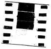
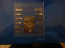
today i made this ,good improve of signal,better than glass dielectric:)

thanks to satcom and doktorofsat:-worship

I saw your post on the Conical Scalar. You did a really good job of fabricating.

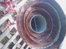
I was in hopes that you would try Doctorofsat's resonator plate. Please tell me how much inprovement it made for you. If possible please post a picture of it int the throat of the lnbf and give details of what materials you used.

Thanks,

Satcom1
 
Satcom1 said:
nelson_b

Thanks for that review of the LNBF. I have the same LNBF and the older BSC-621. Neither work on C/Ku for an offset dish. LAK7 on the u.s. site has his working on a 10' Prime Focus BUD.

Most people by one of these and it winds up on the shelf.

The only proper c/Ku set up is described in this Pic.

On the issue of the flat Scalar on an offset dish some here feel it has to do with the dish f/d ratio.

hi --
nice pictures of the proper C/Ku setups --
if i ever own a large prime focus dish -- that is the type of thing i would be fitting to it --

my - DMX741U - "IS" sitting on a shelf - :-rofl2

you asked -- quote --

Nelson_b I must have missed the thread about your use of a conical Scalar on a 1.8 m offset dish. Can you tell me if this device improves your signal over a flat Scalar? On 1.2 m CM offset many report no difference.

the answer to that is yes .
on my setup - 1. 8 channel master + pauxis c band l.n.b.
the conical scalar is slightly better than the flat scalar --and certainly more suitable -- to get the good signal using the flat scalar - i had to hold it in mid air 3 or 4 mm in front of the mouth of the l.n.b --:) --

regards nelson.b
 
hi satcom1 the f/d on the dish i am using at the moment is 0.45 i am using the doctorofsat plate,the f/d of my old dish using connicle scaler was 0.6,
 
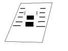
hi doctorofsat i played around with your plate design and found the strips on the edge instead of large strip then tapering to small i changed it so that it started with small then larger and back to small the signal seemed to be better on ertu at 1w plus an improvement on other sats.
 

Attachments

  • img031.webp
    img031.webp
    25.2 KB · Views: 209
Hi friends ..
Managed to find some time to make one of DOS's plates ..
Preliminary tests on a foul rainy day prove interesting though not yet conclusive ..
My first test was the Pentagon channel on 1 West ..
With my T plate I'm get a badly broken pixelated picture today ..
..but not unexpected in these weather conditions ..
Sadly No picture at all using the DOS plate ..
However ..
Switching to Nile Drama (ERTU) on same sat ..produced solid pictures with the DOS plate ....as it does with the T plate ..
On this channel there was little or no difference in signal level with either plate ..
..But on the Pentagon channel ..the difference was considerable..
I'll try some more experiments when the weather improves ...

btw ...what are you guys using to stick the foil to the plastic ?
I'm currently using a simple glue stick ...but its anything but permanent ..
I'm thinking of cutting another piece of plastic to form the outer layer of a foil sandwich ..
This will increase the overall thickness to 2mm ...but will stop the foil strips becoming loose..

rgds 2 all
VS
 

Attachments

  • DP1.webp
    DP1.webp
    79.3 KB · Views: 282
Satcom1 said:
I saw your post on the Conical Scalar. You did a really good job of fabricating.

I was in hopes that you would try Doctorofsat's resonator plate. Please tell me how much inprovement it made for you. If possible please post a picture of it int the throat of the lnbf and give details of what materials you used.

Thanks,

Satcom1
hi
today a made a test between the dielectric of doktorofsat and one made of glass.for this test i used my new conical scalar ring on yamal 49e.

in these transponders are indicated first the quality signal with "dielectric doktorofsat" and then with dielectric of glass

3953 45 0
3870 50 40
3976 50 35
3982 40 40
3987 50 30
4066 35 0

these are the good news,but there are some bad news,for example at 40e
3675 0 50
and at 5w
4154 0 45
comments will be apprectiated for this tests:)
regards
 

Attachments

  • IMAGE_033.webp
    IMAGE_033.webp
    202.3 KB · Views: 245
hi vipersan i made the plate with ali cooking foil and double sided tape
 
Hi Pride ...
I too used cooking foil ..as chocolate tends to be wrapped in something else these days .. ;)
@ Doktor ...
Is there a right way and a wrong way to insert the plate into the feed throat ?
Should the taper formed by the foil point into or out of the lnbf ?

I read that experimentors are trying both options ...but which is the correct option for your design ?
rgds
VS
 
Hi all ..
Have just ordered some adhesive backed copper ...
The kind of thing used to electrically screen guitar pickups ...
Any reason why I should not use this instead of aluminium foil ?

I plan to give it a try anyway ...unless there is a reason why it would not work ..
rgds
VS
 
Vipersan said:
Hi all ..
Have just ordered some adhesive backed copper ...
The kind of thing used to electrically screen guitar pickups ...
Any reason why I should not use this instead of aluminium foil ?

I plan to give it a try anyway ...unless there is a reason why it would not work ..
rgds
VS

If one were to take a piece of PCB material and draw on the pattern with a resist pen such as a Sharpie permanent marker it then could be etched.

A solution of 1 part Muratic Acid to 2 parts Hydrogen Peroxide makes a good and safe agent.
 
Satcom1 said:
If one were to take a piece of PCB material and draw on the pattern with a resist pen such as a Sharpie permanent marker it then could be etched.

A solution of 1 part Muratic Acid to 2 parts Hydrogen Peroxide makes a good and safe agent.

Hi Satcom ...
I had already considered the etching option ....as I still have some Ferric Chloride crystals somewhere in the shed ..
The only thing that put me off ..was the pre etch pcb materials I had ...was copper clad compressed paxolin type stuff ...similar to that used in veroboard..
I suspect it might well be an option if fibreglass pcb material was used instead.
rgds
VS
 
hi vipersan the main part of the plate with the 3 large parts i put in lnbf first i tried the other way but ertu on 1w goes,as i posted before i changed the outside strips so its taper to large then taper it seemed to improve on signal,you have to try different things.
 
Vipersan said:
The only thing that put me off ..was the pre etch pcb materials I had ...was copper clad compressed paxolin type stuff ...similar to that used in veroboard..


How do you know paxolin is not a dielectric ? , besides copper plate works very well at these frequencies, foil is not a great contender

The copper parts on a veroboard (last used it in 1980) might be an ideal way of cutting the various tracks to give the best performance at one frequency( or a good performer at all). Use the single dotted 1mm stuff and cut out/replace as necessary.

From the original Doktorofsat plan I can see a transform design that is very efficient at mid-frequency (3.7-3.8GHz), but not over the whole band.

(Then again I was working on focal alignment with deflection coils at college, and getting disheartened, finally submitting designs for some fixed polarity mechanical porting in the early nineties).
 
You may well be right CH ...
As you rightly say the paxolin type board material may well be a suitable dielectric material ..
In reality I simply have no idea of its 'qualities'
I guess experimentation is the only way to find out.
I simply assumed that glass fibre would be more suitable.
As to vero ...would the holes in the tracks not cause problems ?...or are they not a factor at these frequencies..
rgds
VS
 
Channel Hopper

I'll try to find some copper and stick it on the a thin plate

If the plate has 2-3mm the reception is not good at all I try it believe me , and get mad :) 2-3% amplification...too small

When I use an 0,7-1mm plate always got good results.I hope that using Cu instead of Al , I'll notice some improvments:cool:

The distance between the stripes are important.With actual distance it;s a better amplification on 3600-3900 MHz .I write in my early posting , be free "2play" a little with distances between the 2 column of stripes (6 pieces/column)

You can put even more big elements in the middle !I try with succes , playing with an 0,5mm copper wire and making some spirals.:cool: I made 2 spirals like in photo and put them verticaly on the both side of short stripes
I got even an extra 8-10% on certain freq!!Pretty cool, isn't it?!

vipersan, pride21, satcom1 and other fell free to make experiences with the plate and of course post the result.
At my QTH is a bit cold outside even at daytime but I'llmade an another plate for several testing.And I work hard on my next 1,8m pfta dish, and believe my it takes a lot of time ;)

Best Regards

DoktorOfSat
 

Attachments

  • spirals.webp
    spirals.webp
    4.9 KB · Views: 202
Thanks for the extra info Doktor..
Hopefully my adhesive copper should be here within the next few days (assuming no more postal strikes) ...then I too can experiment a bit more..
Also ...do I take it from your last picture that this also is showing the correct direction to insert the plate for maximum gain ?

ie ..the top of the photo towards the lnbf antenna within the throat ..
rgds
 
Vipersan said:
As to vero ...would the holes in the tracks not cause problems ?...or are they not a factor at these frequencies..
rgds
VS


No problem at 4GHz at all, the wave cycle at C-Band is upwards of 7cms, one reason the signals can also breach foil coatings without too much difficulty.
 
It;s a pleasure for me to give infos!

BTW, I made the scheme in Paint:) in a hurry

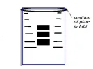
Vipersan and others of course the best position of plate is with short stripes at the entrance of lnbf.Please check the photo
 

Attachments

  • VIPE.webp
    VIPE.webp
    6.5 KB · Views: 250
pride21 said:
hi vipersan the main part of the plate with the 3 large parts i put in lnbf first i tried the other way but ertu on 1w goes,as i posted before i changed the outside strips so its taper to large then taper it seemed to improve on signal,you have to try different things.

hi - pride21 -- i made another plate tonight -- taper to large then taper -- as in post 44

--- this gave - me also - a slight improvement over original plate
--can now "just" pick up the AFN t.p. 4175 R - 28000 at 1 west --
never had a hint of signal from this transponder before :)

regards nelson.b .

-- p.s. -- using 1mm perspex -- co-op tinfoil - on double-sided tape

View attachment 25403
 

Attachments

  • pentagon 40%.webp
    pentagon 40%.webp
    15.1 KB · Views: 156
Excellent news Nelson..
Congrats on your first taster of AFN
..hopefully further 'tweaking' will get you a full pixel free picture even in bad weather on this particularly difficult mux..
..not that there is a great deal to see except on 'pentagon' ...but still its a bit of a buzz adding another notch to your belt.
;)
really pleased for you..
VS
 
Back
Top