Echostar sr8700 power supply schematic

harm lok

Member
My Satellite Setup
echostar / pace / aston
My Location
The netherlands
My echostar SR8700 (old fashion) analog / d2 mac receiver / positioner stopped working. In the system there is a HPS power supply , i think this must be the problem.
There are is not any optical damage so i am looking for the schematic. Maybe there are already members which have repaired experience with this power supply.
Hope someone can help me
 
 
here you are
@harm lok
With ref to the schematics supplied by Trust1: Most of the linked threads mentions capacitor failure, but if the unit is totally dead then also take a look at the RT1 NTC (Negative Temperature Coefficient) surge suppression resistor in series with one of the incoming supply conductors. I have come across reports of a number of examples (notably, it seems, with certain models of KEF sub-woofers!) where the NTC resistor has gone open-circuit bcause slightly too low a value &/or wattage was chosen and so they overheat and fail after a period of use.
 
I have exactly the same issue so if I solve this before you do, I'll reply back.
 
Thanks for your quick responses. The diagram and layout off the power supply of my SR8700 is different from the LT8700 schematics. Although some
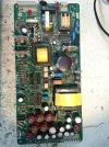
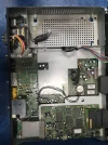
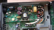
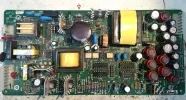
parts of the circuit seem to be the same. The rectified voltage of 240 v is present but the power supply does not switch. I have enclosed some photo's from the power supply board and the overview of the SR8700. Unfortunately the NTC (also RT1 on this board) is not defect. So i have to search further. There is a spot at the inner top plate above the 2000 uF capacitor so i wil solder it en test it separately. If someone recognize the board and maybe some clues please respond.


powersupply_sr8700.jpgpowersupply_sr8700.jpgpowersupply_sr8700.jpgInside_SR8700.webp
 
Sorry Harm , in my hurry to help , did'nt look well .
Steve at Sat4all has a schematic database , maybe You find it there .
 
Llew has mentioned previously the two receivers share the same PSU.
 
Looks to me R5 is allready replaced once , maybe needs attention .powersupply_sr8700.webp
 
Can confirm that my LT8700's PSU looks different, though perhaps functionally the same.
......
There's this too Echostar LT8700 satellite receiver FAQ
That link mentions R18/19 failures but failures in any of the components around/including CR4/5/6/8 & Q9/Q2 might cause a similar issue.because that would stop the switching voltage being applied to the transformer SM1

Edited: just had another thought: the level of the rectified DC across the big primary-side smoothing cap should much nearer to 350-400V DC than 240V, so something seems to be pulling that rail down to below what the switching cct needs to drive SM1 - or am I misinterpreting what @harm lok wrote in post #6?
 
Last edited:
The more I think about this, the more I am inclined to guess that the fault is somewhere around the group of components I mentioned in post #12 - and specifically the CR8 (which is reverse-biased for 1/2 of of the drive cycle to SM1) because, if that has gone s/c then the high voltage DC rail will be pulled down by the voltage divider formed by R18 and Q2, and the circuit won't be able to "flip-flop" to provide the HV drive square-wave to SM1.
 
Hmmmm. I just measured all the output voltages and all seem as per the PDF file. Not sure why the receiver isn't powering on.... Need to poke elsewhere.
 
Found this topic
Llew wrote :
I've got the SR8700, which uses the same power supply AFAIK. Seems like you've lost power to the display board.
If you can reel off the voltages you have from the PS, I could check it against mine (if mine's still working, it's been idle for a few years...)

Later : OK, I'll fire up mine and do a check when I get a chance. I've got a schematic for the SR8700 mainboard somewhere in my files;

Maybe the files still exists included the powerboard .
 
Looks to me R5 is allready replaced once , maybe needs attention .View attachment 130225
And that big power supply cap below that resistor looks to be a bit domed up, put a straight edge across it and see, (with the power off) then again it may just be the lighting.
 
And that big power supply cap below that resistor looks to be a bit domed up, put a straight edge across it and see, (with the power off) then again it may just be the lighting.
could be a reason that there is only a rectified voltage of 240 v instead of approx. 300 v
 
At first , many thanks for all your response and reactions.
Today i have done some more component inspection. The resistor R5 is probberly exchanged in a earlier repair. I think they have placed it without removing the pcb.
I have the resistor measured and mounted again in a proper way. It was not defect. Also i have tried to find and measure the parts jeallen01 mentioned in his reply. But it is very difficult to find te parts related to the lt8700 schematic and this pcb does not have the same component numbers and layout. I have tried again to find the original SR8700 power supply schematic or the technical refference , but no results sofar. I found a documentation site with the servicemanual but unfortunately the site operator is in lock down. I have to continue my search .. At the back site of the powerpcb there are lot of smd components wich are difficult to recognise without a good schematic.
Tomorrow i wil measure the thrue-hole diodes , transitors and capacitors at the upper side of the pcb. It is not the perfect job , but maybe i find the broken part.
I wil send a update after my search..

 
At first , many thanks for all your response and reactions.
Today i have done some more component inspection. The resistor R5 is probberly exchanged in a earlier repair. I think they have placed it without removing the pcb.
I have the resistor measured and mounted again in a proper way. It was not defect. Also i have tried to find and measure the parts jeallen01 mentioned in his reply. But it is very difficult to find te parts related to the lt8700 schematic and this pcb does not have the same component numbers and layout. I have tried again to find the original SR8700 power supply schematic or the technical refference , but no results sofar. I found a documentation site with the servicemanual but unfortunately the site operator is in lock down. I have to continue my search .. At the back site of the powerpcb there are lot of smd components wich are difficult to recognise without a good schematic.
Tomorrow i wil measure the thrue-hole diodes , transitors and capacitors at the upper side of the pcb. It is not the perfect job , but maybe i find the broken part.
I wil send a update after my search..


Since the board does have the legend HTS on it, (Houston Tracker Systems), it could be common to another Echostar design for the US.

Have you tried asking the same question on any sites Stateside ?
 
Since the board does have the legend HTS on it, (Houston Tracker Systems), it could be common to another Echostar design for the US.
The HTS legend is at the upper left corner. I have searched the net for Houston Tracking Systems without a any result. I have only found articles related to the power supplies on this forum.
 
Back
Top