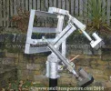
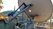
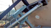
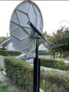
Just Sharing This My Channel Master 1.8 project.

To get a 180 degree movement the actuator arm would have to be on top of the polar bearing.

Exactly. That would be the factual theoretical maximum, to which I did my calculations.
And I described the outcome of the calculation in relation to that 180 degrees/zero-position, as I indicated clearly.
Nothing wrong with that.
And no ~15% off (or whatever percentage, and however calculated).
The fact that the zero-retraction (and the 180-extension) can not really be reached in actual practise, does not alter the calculated angles.

So all this just distracts attention from the fact, that you can choose your zone of highest accuracy, by choosing the ratio of actuator fixing point distances.
And that choice also affects the accuracy for the more extended actuator zone, so it looks to me that it could be worth consideration, what ratio you choose. The effect, of course, is not huge. But the effect is there.

Could be, of course, that no-one ever considered the matter, in practise?

Could be that everybody only focussed on actuator length... (which, of course, also adds accuracy, when you in fact use the extra length by using new fixing points), but without consideration of the mounting distances ratio?

A33

Edit: few textual improvements.
 
Last edited:
Could be that everybody only focussed on actuator length...


Not everyone, see my reply in post 162 above.


The two actuator fixing points and the bearing rotational axis point define the scalene triangle of the actuator plane.

Two sides of this triangle are of fixed length that does not change.
The remaining side of this triangle changes as the actuator arm extends and retracts and so does the E/W angle that the dish is aiming at.

By adjusting the location of the actuator fixing points, the sensitivity of actuator movement and E/W sdjustment can be increased or decreased.
It is simply a matter of how much the thread pitch inside the actuator moves the arm and how much change of E/W degrees are associated with the thread pitch for the scalene triangle setup on the mount.
Different size scalene triangles on a mount will have different levels of sensitivity.
 
Not everyone, see my reply in post 162 above.


The two actuator fixing points and the bearing rotational axis point define the scalene triangle of the actuator plane.

Two sides of this triangle are of fixed length that does not change.
The remaining side of this triangle changes as the actuator arm extends and retracts and so does the E/W angle that the dish is aiming at.
That is not quite true since the rose joint of the actuator forms part of the triangloid and the geometry and position changes during the extension of the motor arm.
 
That is not quite true since the rose joint of the actuator forms part of the triangloid and the geometry and position changes during the extension of the motor arm.


It is accurate enought to setup a 1.8m channel master on a polar mount and generate a few calculations to assist with the process, if required.
Splitting hairs aint gonna sort anything out.

I think we have gone off topic enough now, me included, we should leave the OP to get on with his installation and dish alignment.
C'mon "manik" lets 'ave some tasty fringe guff to chew on...
 
Exactly. That would be the factual theoretical maximum, to which I did my calculations.
And I described the outcome of the calculation in relation to that 180 degrees/zero-position, as I indicated clearly.
Nothing wrong with that.
And no ~15% off (or whatever percentage, and however calculated).
The fact that the zero-retraction (and the 180-extension) can not really be reached in actual practise, does not alter the calculated angles.

So all this just distracts attention from the fact, that you can choose your zone of highest accuracy, by choosing the ratio of actuator fixing point distances.
And that choice also affects the accuracy for the more extended actuator zone, so it looks to me that it could be worth consideration, what ratio you choose. The effect, of course, is not huge. But the effect is there.

Could be, of course, that no-one ever considered the matter, in practise?

Could be that everybody only focussed on actuator length... (which, of course, also adds accuracy, when you in fact use the extra length by using new fixing points), but without consideration of the mounting distances ratio?

A33

Edit: few textual improvements.
Not just at the 180 degree point , at close to 0 degree there is also an error since the two end points of the actuator can never actually meet up. The minimum I have been able to attain is some 2" and that is with cutting back or sacrificing the weather boot on the end of the arm.

On a 1.8m dish it would equate to another 5 or so degrees of error within your calculations

In almost all polarmount systems for real enthusiasts, where there is no restriction to full travel (often the wall the mount is bolted to means a compromise) I have tried to use the largest actuator feasible, with the rotating points set as far from each other as is possible, creating a near equilateral triangle around true south. This often means drilling custom holes in the metalwork fore and aft to enable the ideal position Not only are the forces minimised in movement east and west giving the positioning box an easy life, the pulses from the actuator remain relatively linear on a per degree basis until near the extreme ends of actuator travel.

Slightly off topic, many years ago for one client where there was no chance of getting the dish to the low elevation satellites (and at the same time keep it hidden from twitching curtains on the balcony opposite), I used a scissor arrangement (not unlike a car jacking unit) to keep the actuator parallel to the polarmount just to keep the feedarm from extending over the rails.
 
dans une monture polaire il y a trois angles important :
-l angle polaire qui est fixe sur le site ou on s installe
-l angle de declinaison qui varie en fonction du satellite visé
-l angle d azimuth qui varie aussi en fonction du satellite visé
mais il ne faut pas que l angle d azimut varie si on modifie l angle de declinaison .
dans le post #1 on voit que le verin de declinaison agit sur l angle polaire et ce n est pas la bonne methode.

in a polar mount there are three important angles:
- the polar angle which is fixed on the site where we build the mount.
- the angle of declination which varies according to the targeted satellite
- the azimuth angle which also varies according to the targeted satellite but the azimuth angle must not change if the declination angle is modified.
in post #1 we see that the declination actuator acts on the polar angle and this is not the correct method.

here is an polar mount example , this is the good way to create a mount
 

Attachments

  • mont3.webp
    mont3.webp
    56.9 KB · Views: 73
Last edited:
dans une monture polaire il y a trois angles important :
-l angle polaire qui est fixe sur le site ou on s installe
-l angle de declinaison qui varie en fonction du satellite visé
-l angle d azimuth qui varie aussi en fonction du satellite visé
mais il ne faut pas que l angle d azimut varie si on modifie l angle de declinaison .
dans le post #1 on voit que le verin de declinaison agit sur l angle polaire et ce n est pas la bonne methode.

in a polar mount there are three important angles:
- the polar angle which is fixed on the site where we build the mount.
- the angle of declination which varies according to the targeted satellite
- the azimuth angle which also varies according to the targeted satellite but the azimuth angle must not change if the declination angle is modified.
in post #1 we see that the declination actuator acts on the polar angle and this is not the correct method.

here is an polar mount example , this is the good way to create a mount

i got a exact polarmount copied from those pics the same as the one you have posted,a local welder/fabricator made it.
it would easily handle a 2.4m or bigger dish all made from 9mm steel.

mine is a serious piece of kit and manufactured beautifully.
 
i got a exact polarmount copied from those pics the same as the one you have posted,a local welder/fabricator made it.
it would easily handle a 2.4m or bigger dish all made from 9mm steel.

mine is a serious piece of kit and manufactured beautifully.
9mm steel... how much does it weigh?? Post a thread with some photos of it B)
 
9mm steel... how much does it weigh?? Post a thread with some photos of it :cool:
lets just say you would not run away with it :D

will try to get pictures up soon.
 
that my friend is called sarcasm!

I hear so much contradicting advice. "a 12" jack will be fine" - "no, an 18" is more than enough" - so, to place it safe i go for a 24" and then you say i should start with a 36"
 
that my friend is called sarcasm!

I hear so much contradicting advice. "a 12" jack will be fine" - "no, an 18" is more than enough" - so, to place it safe i go for a 24" and then you say i should start with a 36"
So, filter out the advice that won't work for you.

Tha largest actuator I have used has been the 48" and that was sufficient to run a 2.7 prime focus reflector for about 12 years.
 
Not everyone, see my reply in post 162 above.

I noticed that!
In fact, I quoted you on it, in post #171.
As not many people refer to the triangle, when talking about rotation. But the triangle is indeed the basis! :)

It is accurate enought to setup a 1.8m channel master on a polar mount and generate a few calculations to assist with the process, if required.
Splitting hairs aint gonna sort anything out.

It was not just splitting hairs, it was actually wrong from him. Because the triangle that you refered to, was about the fixing points, not about the rose joint, or however that is called. So you were actually very right.

Same happens where he writes about "... another 5 or so degrees of error within your calculation", seemingly referring to my calculations.
There is no error in my calculation. It is an error to call something an error when it is in fact no error at all.

The fact that after the calculation, you have to take some other factors into account for some relevant practical situation, does not mean that there is an error in the calculation.

I'm afraid I don't think, that he is able to understand this, alas ....

And by the way, the exact equation to calculate the actuator length out of a USALS angle can be found easily here, on this forum.


Greetz,
A33
 
I noticed that!
In fact, I quoted you on it, in post #171.
As not many people refer to the triangle, when talking about rotation. But the triangle is indeed the basis! :)


It was not just splitting hairs, it was actually wrong from him. Because the triangle that you refered to, was about the fixing points, not about the rose joint, or however that is called. So you were actually very right.

Same happens where he writes about "... another 5 or so degrees of error within your calculation", seemingly referring to my calculations.
There is no error in my calculation. It is an error to call something an error when it is in fact no error at all.

The fact that after the calculation, you have to take some other factors into account for some relevant practical situation, does not mean that there is an error in the calculation.

I'm afraid I don't think, that he is able to understand this, alas ....

And by the way, the exact equation to calculate the actuator length out of a USALS angle can be found easily here, on this forum.


Greetz,
A33
In post #181 you confirmed they were your 'calculations'.

The start and finish points might be acceptable on paper but are entirely impractical in the real world (the choice to ignore the rose joint less so but still a faux pas in polarmount design).

It would be somewhat foolish to rely solely on limit switches to prevent an angle where the actuator shaft gets close to the polar bearing point for obvious reasons.
The additional plate within the o/ps kit might be essential fitment to avoid such a scenario from occurring, the side effect of its inclusion being an inabilty to use one of the shorter actuators on the completed assembly.
 
I built my mount respecting the triangle mentioned by channel hopper and A33 (345mm x 345mm), I can go very far west and east but +/- 70° no more I am using a 24 inch (QARL24) actuator but need 500mm (more than 18 inch)
if you make full use of a bigger actuator, it takes longer to move...

below my actual mount without motorised elevation
 

Attachments

  • para1.webp
    para1.webp
    91.6 KB · Views: 62
  • para2.webp
    para2.webp
    67.6 KB · Views: 55
  • para3.webp
    para3.webp
    90.7 KB · Views: 51
  • para4.webp
    para4.webp
    113.2 KB · Views: 62
Last edited:
I built my mount respecting the triangle mentioned by channel hopper and A33 (345mm x 345mm), I can go very far west and east but +/- 70° no more I am using a 24 inch (QARL24) actuator but need 500mm (more than 18 inch)
if you make full use of a bigger actuator, it takes longer to move...

below my actual mount without motorised elevation
Very nice. A bigger actuator that properly complements the polarmount provides more counts per degree.

In the other thread you have sent confirmation of receiving 72.1 degrees. What is the absolute extreme East and West of your system ? On the 1.8m I have upstairs the reflector grounds out at 73 degrees to the east and 71 to the west, or roughly 3-6 degrees above the horizon. But that is with a 36".

Despite being a prime focus front end with counterweight your overall arc of coverage should give the o/p something factual to look forward to.
 
Very nice. A bigger actuator that properly complements the polarmount provides more counts per degree.

In the other thread you have sent confirmation of receiving 72.1 degrees. What is the absolute extreme East and West of your system ? On the 1.8m I have upstairs the reflector grounds out at 73 degrees to the east and 71 to the west, or roughly 3-6 degrees above the horizon. But that is with a 36".

Despite being a prime focus front end with counterweight your overall arc of coverage should give the o/p something factual to look forward to.
just one question, with a channel master of 1m20 you manage to go from where to where?
With the arm on the left I am limited in movement towards the west, after a certain limit the actuator is parallel to the axis of the antenna and tilts.

1643289528082.webp
 
Back
Top