
- Forums
- Satellite TV receivers & systems support forums
- DISH SETUP: Single sat, Multi-Sat & Motorised
You are using an out of date browser. It may not display this or other websites correctly.
You should upgrade or use an alternative browser.
You should upgrade or use an alternative browser.
Precision 2.2 metre Antenna Install
- Thread starter moonbase
- Start date
A
archive10
Guest
Yes, but why??Hi,
The Precision 2.2m antenna with Ku band feed support arms, Ku feed and C120 waveguide adapter are now listed for sale in the forum classifieds.
Rgds

Hi,
As the sale of the Precision 2.2m antenna has been temporarily put on hold I have decided to continue with this installation for the time being.
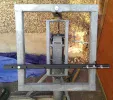
The next stage of the installation is to adapt the original Precision polar mount for inclined orbit tracking. As I do not wish to modify the structure of the Precision polar mount, the inclined tracking will be setup using "Add Ons" that bolt onto the existing frame.
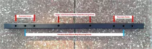
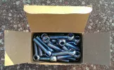
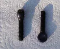
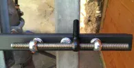
The pivot axis will be from a length of square box section that bolts onto the existing polar mount frame via the two bolt holes on its vertical struts. The pivot points will be created using eye bolts and threaded rod at each side of the polar mount. Its a similar design to the one created by "Captain Jack" on one of his install topics, I have only made some very small changes.
The advantage of using the above method is that it can be upscaled for a larger Precision/Elite antenna with a 1200mm rear mounting ring. The polar mount is easily capable of accepting an antenna larger than 2.2m, the only additional need would be a longer length of the box section with increased square size and wall thickness. The eye bolts could also be increased in size although the existing ones are rated at 2486kg per bolt for the black ones and 1193kg per bolt for the shiny ones.
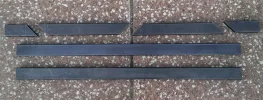
Just as a footnote, the picture of the pivot axis bar shows the two holes that can be used to mount the bar on a Jaeger 1224 channel master plate. Please note that I have no intention of trying to mount the Precision 2.2m antenna onto a Jaeger 1224 H-H motor. It's just to show that the same pivot axis bar can also be used on a smaller antenna up to 1.8m diameter with a suitably "beefed up" Jaeger 1224.
I have attached some pictures below of the parts and how they wil go together for the pivot axis. More pics to follow later showing the elevation actuator mounting.
Rgds
As the sale of the Precision 2.2m antenna has been temporarily put on hold I have decided to continue with this installation for the time being.
The next stage of the installation is to adapt the original Precision polar mount for inclined orbit tracking. As I do not wish to modify the structure of the Precision polar mount, the inclined tracking will be setup using "Add Ons" that bolt onto the existing frame.
The pivot axis will be from a length of square box section that bolts onto the existing polar mount frame via the two bolt holes on its vertical struts. The pivot points will be created using eye bolts and threaded rod at each side of the polar mount. Its a similar design to the one created by "Captain Jack" on one of his install topics, I have only made some very small changes.
The advantage of using the above method is that it can be upscaled for a larger Precision/Elite antenna with a 1200mm rear mounting ring. The polar mount is easily capable of accepting an antenna larger than 2.2m, the only additional need would be a longer length of the box section with increased square size and wall thickness. The eye bolts could also be increased in size although the existing ones are rated at 2486kg per bolt for the black ones and 1193kg per bolt for the shiny ones.
Just as a footnote, the picture of the pivot axis bar shows the two holes that can be used to mount the bar on a Jaeger 1224 channel master plate. Please note that I have no intention of trying to mount the Precision 2.2m antenna onto a Jaeger 1224 H-H motor. It's just to show that the same pivot axis bar can also be used on a smaller antenna up to 1.8m diameter with a suitably "beefed up" Jaeger 1224.
I have attached some pictures below of the parts and how they wil go together for the pivot axis. More pics to follow later showing the elevation actuator mounting.
Rgds
Attachments
Last edited:
blademedia
Member
- My Satellite Setup
- Sky
- My Location
- UK
It looks good, nice work well done Dave.
Hi,
Today's offering is the fabrication of the polar mount inclined tracking bracket that secures the elevation actuator to the polar mount outer frame.
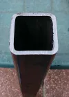
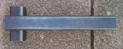
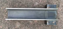
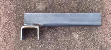
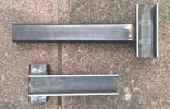
The inclined tracking bracket is an "Add On" that bolts onto the polar mount using an existing hole in the top horizontal section of the outer frame. The box section for the polar mount outer frame is 50mm square so I needed to source some U section steel that had an inner diameter of 50mm. This proved difficult to find so I bought some 60mm square box section steel with 5mm wall thickness. By cutting away one side of the box section it was possible to convert it into U section.
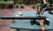
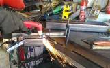
The 60mm box section was cut into lengths using an Evolution mitre saw, they are rated for 3mm wall thichness box section. However, by cutting slowly I managed to get it to cut through the 5mm wall thickness of the box section with reasonably clean cuts. The side of the box section was cut away using a plasma torch then the parts were welded together to create the inclined tracking bracket. I still have to drill the bolt holes in the bracket that secure it to the polar mount and hold the elevation actuator in place.
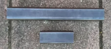
From the one length of box section that I bought, I had two brackets made, one for Precision/Elite antenna with the 600mm rear mounting ring and one for antenna with the 1200mm rear mounting ring.
I wish to thank blademedia for the ideas and sending pictures by email on the the fabrication of the bracket. It was a great help and its a nice simple solution. @blademedia you should offer a service covering design and fabrication to customers wishing for an elite bespoke service of this type.
Pictures are attached below covering the fabrication of the inclined tracking bracket. The forum upload restricts the number of pictures to 10. I have uploaded another 4 pictures to the next post, these 4 pictures show the bracket loosely in place on the polar mount.
Rgds
Today's offering is the fabrication of the polar mount inclined tracking bracket that secures the elevation actuator to the polar mount outer frame.
The inclined tracking bracket is an "Add On" that bolts onto the polar mount using an existing hole in the top horizontal section of the outer frame. The box section for the polar mount outer frame is 50mm square so I needed to source some U section steel that had an inner diameter of 50mm. This proved difficult to find so I bought some 60mm square box section steel with 5mm wall thickness. By cutting away one side of the box section it was possible to convert it into U section.
The 60mm box section was cut into lengths using an Evolution mitre saw, they are rated for 3mm wall thichness box section. However, by cutting slowly I managed to get it to cut through the 5mm wall thickness of the box section with reasonably clean cuts. The side of the box section was cut away using a plasma torch then the parts were welded together to create the inclined tracking bracket. I still have to drill the bolt holes in the bracket that secure it to the polar mount and hold the elevation actuator in place.
From the one length of box section that I bought, I had two brackets made, one for Precision/Elite antenna with the 600mm rear mounting ring and one for antenna with the 1200mm rear mounting ring.
I wish to thank blademedia for the ideas and sending pictures by email on the the fabrication of the bracket. It was a great help and its a nice simple solution. @blademedia you should offer a service covering design and fabrication to customers wishing for an elite bespoke service of this type.
Pictures are attached below covering the fabrication of the inclined tracking bracket. The forum upload restricts the number of pictures to 10. I have uploaded another 4 pictures to the next post, these 4 pictures show the bracket loosely in place on the polar mount.
Rgds
Attachments
-
 Inclined_Tracking_Bracket_01.webp407.6 KB · Views: 32
 -
 Inclined_Tracking_Bracket_02.webp114 KB · Views: 32
 -
 Inclined_Tracking_Bracket_03.webp462.1 KB · Views: 33
 -
 Inclined_Tracking_Bracket_04.webp262.6 KB · Views: 31
 -
 Inclined_Tracking_Bracket_05.webp250.9 KB · Views: 28
 -
 Inclined_Tracking_Bracket_06.webp291.3 KB · Views: 33
 -
 Inclined_Tracking_Bracket_07.webp198.3 KB · Views: 32
 -
 Inclined_Tracking_Bracket_08.webp248.3 KB · Views: 31
 -
 Inclined_Tracking_Bracket_09.webp115.6 KB · Views: 29
 -
 Inclined_Tracking_Bracket_10.webp323.4 KB · Views: 30
Last edited:
Hi,
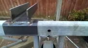
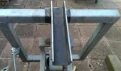
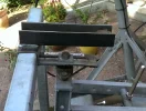
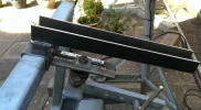
The other 4 pictures referred to in my previous post are attached below. These are the pictures showing the inclined tracking bracket loosely in place on the polar mount.
Rgds
The other 4 pictures referred to in my previous post are attached below. These are the pictures showing the inclined tracking bracket loosely in place on the polar mount.
Rgds
Attachments

Captain Jack
Retired human
- My Satellite Setup
- See signature
- My Location
- North Somerset
I have to get a plasma cutter - those things look awesome... Looking good.
Is the inclined tracking going to adjust the inclination of the whole polar mount and not the declination of the dish? I suppose it makes more sense here since declination with the prime focus will be minimal there won't be much room to maneuver the dish's declination - it will hit the PM...
Is the inclined tracking going to adjust the inclination of the whole polar mount and not the declination of the dish? I suppose it makes more sense here since declination with the prime focus will be minimal there won't be much room to maneuver the dish's declination - it will hit the PM...
I have to get a plasma cutter - those things look awesome... Looking good.
Is the inclined tracking going to adjust the inclination of the whole polar mount and not the declination of the dish? I suppose it makes more sense here since declination with the prime focus will be minimal there won't be much room to maneuver the dish's declination - it will hit the PM...
CJ,
The inclined tracking will be operational on the declination offset angle of the antenna. The antenna will be in a "stand off" type of position with respect to the polar mount frame, it will not be in contact with the frame. Due to the "stand off" position of the antenna I hope to have enough backward and forward tilt to track +/ 10 degrees, possibly more.
Initially, I will use the polar mount elevation and declination adjustments to get an arc without the inclined bracket and elevation actuator being operational. Once I have things OK for a standard polar mount and arc I will lock the polar mount declination angle and put in place the "Add On" for inclined tracking.
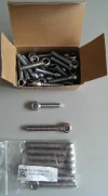
To help with getting the antenna "stood off" from the polar mount I purchased some stainless steel eye lifting bolts. They are 88mm long with an M12 thread and will allow me to get more "stand off" and inclined plane motion with the antenna than the 60mm long eye bolts with M10 thread that I originally planned to use.
I plan to setup a test system using a small 1.5m Precision antenna to check if it works as intended. I hope this will show up any problems and allow me to resolve them before I move over to the 2.2m antenna
I have attached a picture of the eye bolts below.
Rgds
Attachments
Captain Jack
Retired human
- My Satellite Setup
- See signature
- My Location
- North Somerset
Ahh, makes sense now - thanks
blademedia
Member
- My Satellite Setup
- Sky
- My Location
- UK
Nice work MB cracking job well done.
Hi,
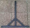
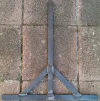
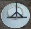
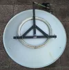
More fabrication offerings today, this time it is the inclined tracking frame that is bolted onto the 600mm rear mounting ring of the antenna.
The 600mm rear mounting rings of Precision antenna are manufactured with 3 boss heads to accept M10 bolts. By securing a frame to the 600mm rear mounting ring it allows M12 or greater size eye bolts to be used as part of the pivot axis for inclined tracking. For a small antenna such as a Precision 1.5m, the weight of the antenna and wind load would be easily within the capacity of M10 eye bolts. For the Precision 2.2m antenna the M10 eye bolts will probably be OK, however, for peace of mind it might be sensible to use a larger diameter eye bolt such as M12.
The frame that fixes to the antenna has been fabricated out of 40mm x 20mm box section in the shape of an inverted T with mitred side support struts. The elevation actuator is attached to the top of the vertical part of the inverted T frame.
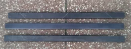
I have attached some pictures below of the frame including a couple of pictures showing how it is located on the 600mm rear mounting ring of the antenna. I used a spare old Precision 1.2m antenna for the illustration, the old 1.2m needs a clean up but it does the job to show how the inclined tracking frame is located.
Rgds
More fabrication offerings today, this time it is the inclined tracking frame that is bolted onto the 600mm rear mounting ring of the antenna.
The 600mm rear mounting rings of Precision antenna are manufactured with 3 boss heads to accept M10 bolts. By securing a frame to the 600mm rear mounting ring it allows M12 or greater size eye bolts to be used as part of the pivot axis for inclined tracking. For a small antenna such as a Precision 1.5m, the weight of the antenna and wind load would be easily within the capacity of M10 eye bolts. For the Precision 2.2m antenna the M10 eye bolts will probably be OK, however, for peace of mind it might be sensible to use a larger diameter eye bolt such as M12.
The frame that fixes to the antenna has been fabricated out of 40mm x 20mm box section in the shape of an inverted T with mitred side support struts. The elevation actuator is attached to the top of the vertical part of the inverted T frame.
I have attached some pictures below of the frame including a couple of pictures showing how it is located on the 600mm rear mounting ring of the antenna. I used a spare old Precision 1.2m antenna for the illustration, the old 1.2m needs a clean up but it does the job to show how the inclined tracking frame is located.
Rgds
Attachments
-
 Inclined_Tracking_Bracket_15.webp276.1 KB · Views: 31
 -
 Inclined_Tracking_Bracket_16.webp283.4 KB · Views: 29
 -
 Inclined_Tracking_Bracket_17.webp459.1 KB · Views: 30
 -
 Inclined_Tracking_Bracket_18.webp523.8 KB · Views: 34
 -
 Inclined_Tracking_Bracket_19.webp253.6 KB · Views: 36
 -
 Inclined_Tracking_Bracket_20.webp282.2 KB · Views: 34