
You are using an out of date browser. It may not display this or other websites correctly.
You should upgrade or use an alternative browser.
You should upgrade or use an alternative browser.
The Aero Thread..
- Thread starter Vipersan
- Start date

smoggy07
Regular Member
- My Satellite Setup
- Sky minidish and Sky + HD 250gig Anytime+ box with full ish appart from sports and movies, Dreambox DM500s clone (Pli Jade3 max var F/W), Motorised 1.1Meter Dish
- My Location
- middlesbrough, teesside, northeast coast, uk

Confucian
Regular Member
- My Satellite Setup
- 1.4m Offset, 1.8m Prime Focus for C Band Aero
- My Location
- Dalystown, Ireland
Read a bit about it but not tried it, have enough trouble with Aero lol
spacedish
Regular Member
- My Satellite Setup
- 1.8PF
90cm Greg
90cm offset
Ka mil lnb
numerous receivers
S band
- My Location
- north west uk

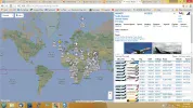
The image above shows just satellite and PiRep plots from Oceanic traffic . As you can see , it's pretty busy.
At present we don't have anyone uploading from the USA and as a result are missing traffic from two westerly birds, but I am hoping that will be addressed this weekend.
There are some very interesting movements , which until now have gone unnoticed , including top level mil/DoD flights from the US to central Africa[Chad]
Last weekend we had all the Obama circus fleet appearing .
Thanks to the likes of "C" , Scopus , Paul , Andy and our other satellite stations we are now seeing 20,000 unique position plots for Oceanic traffic each day.
The next version of PP will be released shortly which will contain even more enhancements and allow us to separate PiRep and satellite traffic. Updates are of course free to registered users.
On the subject of inclination , I agree with VS about dish size.
My 1.8 can just about maintain a useable signal on 25east which is just under 2 degs inclined....but for anything with a bigger "wobble" the 1.2 should be better , even though you'll see some missed/bad packets.
Confucian
Regular Member
- My Satellite Setup
- 1.4m Offset, 1.8m Prime Focus for C Band Aero
- My Location
- Dalystown, Ireland
Ahhhh I see, I thought it might be important !!!! lolIts a piece of self amalgamating tape to waterproof your F connector .
I used heat shrink and a blob of grease.


scopus
Specialist Contributor
- My Satellite Setup
- Primesat/Famaval 1.8 PF C/ku/Ka, Octagon SX8HD1, SX88, Openbox S3 Mini HD-V8S Freesat V7 HD-V8 Finder, Amiko A4K Combo, Satlook Colour HD Spectrum, Sansui A909 Amp and BOSE Acoustimass speakers for the audio.
- My Location
- Staffs UK
Depends on the FD ratio of the dish, I always employ the 'poke and hope' method, seems to work for me;)
s-band
Member
- My Satellite Setup
- 1.5m IRTE PF, Invacom SNF-031, TBS6983,
Various L, S, C, X & Ka bits. 1.2m S/X/Ku/Ka Prodelin on Az-El (being refurbished), 1.8m Precision PF with Bullseye Ku LNB or various C & X bits
- My Location
- Essex
IMO, the position of the feed phase centre, relative to the dish focus, is the most important thing with the scalar position secondary.Next Question
How far into the conical scalar should the Lnb go. ?
Is there a "formula or is it "poke & hope" ?
I use EBSPRO's Android app and tweak the position of the feed/scalar. If there's nothing that EBS can work with, I use an Android VNC client (RealVNC) to view the beacon level on SDR# running indoors.
Having said all that, poke & hope seems to get within a dB half the time.
Edit - another couple of things that may give you an extra dB or 2:
Try both polarisations moving the plate to get the right sense of circular
Also move the dielectric plate in and out to optimise signal
Last edited:

John
Enthusiast.
- My Satellite Setup
- Elite 2.2 PF with Multi lnb changer - CM1.2 - Gibertini 1.25.
Ku - Ka - Ext Ku - C & Ext C. X.
PC cards 6983,6903, main receiver GTX Combo. Ericsson RX8200.
Promax HDRanger+ & HDRanger2 Analysers.
- My Location
- North Nottinghamshire. UK.
[QUOTE="scopus, post: > I always employ the 'poke and hope' method, seems to work for me;)[/QUOTE]<
... I'm saying nowt
... I'm saying nowt
Last edited:
Confucian
Regular Member
- My Satellite Setup
- 1.4m Offset, 1.8m Prime Focus for C Band Aero
- My Location
- Dalystown, Ireland
Try both polarisations moving the plate to get the right sense of circular
Sorry for being dim how do you mean "moving the plate to get the right sense of circular"
Last edited by a moderator:

aceb
Specialist Contributor
- My Satellite Setup
- TBS 6925
1.8m Precision + PLL Bullseye, motorised but probably siezed now.
2 x Sky Zone 2 for 28/19/13°E
- My Location
- Sussex
Yes, been running it since the very first release in December 2004.
s-band
Member
- My Satellite Setup
- 1.5m IRTE PF, Invacom SNF-031, TBS6983,
Various L, S, C, X & Ka bits. 1.2m S/X/Ku/Ka Prodelin on Az-El (being refurbished), 1.8m Precision PF with Bullseye Ku LNB or various C & X bits
- My Location
- Essex
how do you mean "moving the plate to get the right sense of circular"
Switch polarisation electrically (V to H or vice versa) then turn the plate 90 degrees, looking at the open waveguide. That way you will keep the same circular polarisation but swap the front end electronics/feed. Usually there is a slight difference in performance between V & H electronics/feeds.
Switch polarisation electrically (V to H or vice versa) then turn the plate 90 degrees, looking at the open waveguide. That way you will keep the same circular polarisation but swap the front end electronics/feed. Usually there is a slight difference in performance between V & H electronics/feeds.
s-band
Member
- My Satellite Setup
- 1.5m IRTE PF, Invacom SNF-031, TBS6983,
Various L, S, C, X & Ka bits. 1.2m S/X/Ku/Ka Prodelin on Az-El (being refurbished), 1.8m Precision PF with Bullseye Ku LNB or various C & X bits
- My Location
- Essex
Yet more thoughts....
The scalar ring is mainly to improve the front to back ratio of the feed and to reduce spill over where the feed "sees" ground noise if it covers more than the dish area (especially for PF). In the case of the offset it needs to reduce the beam a bit more than a PF. I guess that for an offset the feed needs to be well inside the scalar. In setting the scalar, it may be better to use the EBSPro route as you can measure S/N directly and it's the N that the scalar will affect most.
If you want the last 0.1dB, it may be worth raising the dish above the building so that any overspill "sees" cold sky as opposed to a warm building.
The scalar ring is mainly to improve the front to back ratio of the feed and to reduce spill over where the feed "sees" ground noise if it covers more than the dish area (especially for PF). In the case of the offset it needs to reduce the beam a bit more than a PF. I guess that for an offset the feed needs to be well inside the scalar. In setting the scalar, it may be better to use the EBSPro route as you can measure S/N directly and it's the N that the scalar will affect most.
If you want the last 0.1dB, it may be worth raising the dish above the building so that any overspill "sees" cold sky as opposed to a warm building.
Last edited:
Confucian
Regular Member
- My Satellite Setup
- 1.4m Offset, 1.8m Prime Focus for C Band Aero
- My Location
- Dalystown, Ireland
how do you mean "moving the plate to get the right sense of circular"
Switch polarisation electrically (V to H or vice versa) then turn the plate 90 degrees, looking at the open waveguide. That way you will keep the same circular polarisation but swap the front end electronics/feed. Usually there is a slight difference in performance between V & H electronics/feeds.
Ah Ha That explains why when I first started looking for 25E I "Theoretically" correctly set the polarization with the Receiver but had to reverse it to get the Channels.
Also the "IF" there isn't any/much difference in the front end electronics I could get away with one psu feeding via 3 x Bias Tee's and set the polarizations with the wedges ????????????
s-band
Member
- My Satellite Setup
- 1.5m IRTE PF, Invacom SNF-031, TBS6983,
Various L, S, C, X & Ka bits. 1.2m S/X/Ku/Ka Prodelin on Az-El (being refurbished), 1.8m Precision PF with Bullseye Ku LNB or various C & X bits
- My Location
- Essex
Yes. Alternatively, use an 18V PSU feeding a 12 V regulator (e.g. 7812) to get both voltages.Also the "IF" there isn't any/much difference in the front end electronics I could get away with one psu feeding via 3 x Bias Tee's and set the polarizations with the wedges ????????????
Confucian
Regular Member
- My Satellite Setup
- 1.4m Offset, 1.8m Prime Focus for C Band Aero
- My Location
- Dalystown, Ireland
s-band
Member
- My Satellite Setup
- 1.5m IRTE PF, Invacom SNF-031, TBS6983,
Various L, S, C, X & Ka bits. 1.2m S/X/Ku/Ka Prodelin on Az-El (being refurbished), 1.8m Precision PF with Bullseye Ku LNB or various C & X bits
- My Location
- Essex
Interesting. The back end specification is subtly different from the R2 and the deal breaker for me is that it doesn't appear to have an external reference input. The upgraded RTL-SDRs with 0.5ppm TCXOs may be better value for sat use.
Worthy of a new thread?