Archived-1
Persona non grata
- Joined
- Apr 14, 2007
- Messages
- 7,570
- Reaction score
- 8,590
- Points
- 113
- My Location
- uk
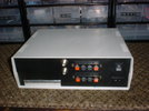
Looks a great job Evan ") well done
well done 
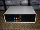
well done well done Yep ..Very nice! You should stick some labels on
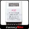
Negligible in standby/idle mode ..VS, how's the heat generation from the power supply?
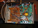
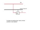
Protection diodes across the relays VS?BUT ...noise IS an issue ...
When I say noise I mean electrical noise..
Spikes etc as the relays switch ..
and this has caused me a few days of head scratching ..and no I dsn't find an easy solution.
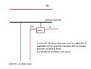
Already fitted Llew ...and along with some 10uH inductors in the supply line and ground line to the 5v regulators ...it improved the frequency of the resetting ..but not completely.Protection diodes across the relays VS?
Any chance you could scan the relevant page(s)...with perhaps a sample schematic which is often given..?I just found my copy of National Semiconductor's "Voltage Regulator Handbook".
(why do things you need disappear and return again when not needed)
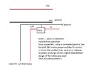
A chapter deals with automotive power supplies and mentions the real specification
of normal voltages in a car, +80 V to - 50 V and not +12-14 V as you might expect.
Anyway, the cure is quite simple with a few well chosen extra components to
limit the voltage spikes. A resistor, a diode, a zener-diode and a capacitor makes
life easier and a normal voltage regulator won't see the horrible stuff on the input
voltage. Examples show 12 to 5 V regulator applications and higher input voltages get the
same treatment.