Advice Needed Advice on faulty V-box II

Blondegirl

Member
My Satellite Setup
1.5m dish 1224 Supermount H to H motor, receiver tbd
My Location
Scotland
I have a V-box II driving a Jager SMR1224.

When we tried to use it the other day, it failed with ER-2

The box clicks (both directions) but comes back with ER-2


Today we looked at it, it appears it moves with no issue and the reed switch is operating correctly.

When closed the switch is 3.0/3.1 ohm (at the V-box – quite a long cable which measures 3.0ohm in itself as a loop) and >100Mohm when open.

If I connect a ~9v battery to the switch with a LED and resistor it pulses as expected and gives the following pulses as measured via an oscilloscopeswitchsatellite.jpg
This appears totally right to me, however the Vbox when connected doesn’t register the switching.

When the switch is open/not connected I measure 0.3vdc - is this the correct expected value?

It looks to me like the V-box is faulty – anyone any experience here in this area who can help?
 
Last edited:
Er2 is a problem connecting with the motor in my experience. Have you tried running a separate two core control cable between the vBox and the motor (I had a faulty lead on one of my dishes). Have you tried moving the motor with a direct 12v supply (not from the vBox.).

If you have double checked those then you could look inside the vBox and change the large caps & rectifier. I did that with an old vBox and got it back to life (important - this vBox had other faults NOT a Er2 error). But it was very fiddly to do, not a quick job.
 
Also check if you've set any limits, on the V-Box II, there is a way to clear all limits, but I can't remember what you press, at the moment, but you should find a manual, online.
 
It was the V-Box!

I decided there was nothing wrong with the dish, so I stripped the V-Box down.

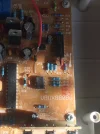
It is a mess inside! there are tracks cut, and loads of badly inserted links/jumpers, and even the board looks like it was left out in the rain for 10 years! - I bought it brand new, never been opened and in the comfort of the living room since purchase - so it came like that!

Anyhow, the voltage to the reed switch should be 5V, internally there is a 7805 regulator feeding a resistor to the reed switch terminals, from the other terminal it has another resistor which feeds an opto isolator.

Everything looked OK, but it appears the connection between the pcb and terminals for the reed switch was split, I soldered a piece of wire to link across the broken track as below now all is well with the Vbox - motor positioner!:

vpos.webp

My addition is the lower-left one with the bend in it, the other is just one of the examples of the links which must have been done before it was supplied!

So all working, just got to re-align everything as it's lost the reference positions

That's for another day!!
 
It could have gotten wet, due to water flowing down a cut/damaged cable, into the V-Box II, or perhaps even from condensation.
Most electrical components appear to be cheaply made, as we seem to be living in a throw away society, where some items are only intended to last a few years.

Well spotted, and repaired, hopefully it will last you a good few years.
 
I think it's the quality of the manufacture, and certainly not due to moisture ingress in the cable, and I doubt condensation.

The state of the board was appalling, I wish I had taken more photos. tracks cut - badly, links that leap over other wires - neither of which are insulated, and just an extremally bad mess overall, I suspect the board was not washed properly after soldering, just enough to leave a residue all over.

I didn't expect Rolls-Royce quality but....

There is throw away quality and then this!
 
I must agree the PCB quality is poor.
I recently opened up my Technomate branded unit as after a long period of powered down I get Er1 when it moves the dish,.
It even shows it when used on the bench with a known good actuator (everything else works fine just showing the error) , has anybody got a circuit diagram for this unit ( pcb marked as VBOX880B ) or any experiance of this?
 
I must agree the PCB quality is poor.
I recently opened up my Technomate branded unit as after a long period of powered down I get Er1 when it moves the dish,.
It even shows it when used on the bench with a known good actuator (everything else works fine just showing the error) , has anybody got a circuit diagram for this unit ( pcb marked as VBOX880B ) or any experiance of this?

If it is this one, or similar, then yes (somewhere)

They all suffer from poorly cleaned boards and you will find they have been worked on at the factory both tracak and component side.

1611843178536.webp
1611843203910.webp
 
Yes that is the one, it would be great if you could dig out the information.
One thing I am going to try is swap the electrlytic caps as the one on the 36V supply looks ok but is only rated at 35V! maybe the over current senses a pull down of the 36V supply during high current draw and is getting confussed by high ripple. Only a guess!
 
Does your positioner have the UK plug fitted ?
 
Yes fitted with a UK plug, thanks for the circuit diagram. I will have to study it closelly as on first glance my theory is way off!
 
That diagram is slightly different than mine, which is the same technomate v-box except mine is version II, that (Box) looks like version III, I see the diagram is version I.

The board is butchered, they wired the feed to the opto isolator (diode side) from the 5V and cut the 12V track, also I don't remember there being a 1n4148 diode (Though I might be wrong), and certain there was no varistor.

@Joolz

You could very well have the same fault as mine, if you have a voltmeter, measure the voltage across the two connectors for the pulse connections, this should be 12V if Version I, or 5V if version II (don't know about III). (with the external wires disconnected)

If it's intermittent or not there, then try on the board measuring between (A) and (B ) as shown below, if this does give a 5 or 12V voltage then the pcb track is split where it connects to the connector - this was my issue, and hence why I soldered the wire that merely joins the bits that the track should have done.

vposconn.jpg
 
Channel Hopper you are a star! your circuit diagram enabled me to fix the fault :p . The resistor R4 on the potential divider was open circuit, So from this I guess if the incoming electronics supply drops (24 vdc on the bench) due to overloading on the other motor drive supply winding? it trips the Er1 error. All back in operation looking at 55°W on C Band
Next job is to sort out the high loss on the RF side when I did a sweep it had a peak loss of 7db! Currently controlling the V Box via a seperate coax.
 

Attachments

  • VBoxOriginal.webp
    VBoxOriginal.webp
    52.7 KB · Views: 34
Blondegirl thanks for the advice and totally agree with your comments on build quality.
 
Channel Hopper you are a star! your circuit diagram enabled me to fix the fault :p . The resistor R4 on the potential divider was open circuit, So from this I guess if the incoming electronics supply drops (24 vdc on the bench) due to overloading on the other motor drive supply winding? it trips the Er1 error. All back in operation looking at 55°W on C Band
Next job is to sort out the high loss on the RF side when I did a sweep it had a peak loss of 7db! Currently controlling the V Box via a seperate coax.
Ah, not my schematic, the honours should go to somebody else on this forum.
 
joolz said :
Next job is to sort out the high loss on the RF side when I did a sweep it had a peak loss of 7db! Currently controlling the V Box via a seperate coax.

in my sf8008 i pick disecq signal before it goes into the tuner .
i put a cable with an rca plug for my positioner . no more loss of signal !!!
 

Attachments

  • dispic.webp
    dispic.webp
    153.1 KB · Views: 30
Back
Top