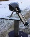
Another Polar-mount for 1,2m Channel Master

RimaNTSS

Super Moderator
Staff member
My Satellite Setup
Some SAT-related hardware.
My Location
N-E from Riga
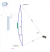
Hi all! I think I've started new project, which is logical continuation of this thread. About 10 or so years ago I've seen the developing of this idea on another forum. But at that time I was not ready, and also not interested to follow it. Basic idea behind this design that continuation of axis of turning goes directly via center of gravity of the antenna. It helps to make system very stable and easy to escape from most-Est and most-West positions. For small antennas that is probably not a big issue, but if you use big&heavy antenna (for example CM120) than the issue could be very actual.
So, I've made a sketch CM120cm_Gravicapa (Custom).webp which I will try to follow and adopt as necessary when get all the parts on hands.
Was looking for 100x100mm square pipe today but could not find :(, so picket up couple of other size pipes IMG_20170120_160957 (Custom).webp . Also purchased Diseqc 1.2 motor and voided its warranty right away as I wanted to look wat is inside IMG_20170120_163810 (Custom).webp . And inside I've got metal 360* gear, so, I think the motor can go more than 160* as it designed originally IMG_20170120_164547 (Custom).webp .
Also ordered couple of bearings, will have them delivered next week.
I hope this project will not be "other, never finished one" :eek:
 
Great stuff! Looking forward to your progress.

Basic idea behind this design that continuation of axis of turning goes directly via center of gravity of the antenna.

Make sure it's the CG of the antenna with arms and LNB, not just reflector...

I hope this project will not be "other, never finished one" :eek:

You get more project finished in a week than I do in a year... :(
There's nothing to worry about! :cool:
 
Make sure it's the CG of the antenna with arms and LNB, not just reflector...
This should not be a problem as whole thing (reflector, feedarms, declination mechanism) will be movable up/down along the pipe.
 
Do not have bearings yet, so can not do much. Just put some parts together to visualize the look of the possible final product.
 

Attachments

  • IMG_20170121_184036 (Custom).webp
    IMG_20170121_184036 (Custom).webp
    144.1 KB · Views: 61
  • IMG_20170121_184204 (Custom).webp
    IMG_20170121_184204 (Custom).webp
    97.3 KB · Views: 61
  • IMG_20170121_191301 (Custom).webp
    IMG_20170121_191301 (Custom).webp
    229.8 KB · Views: 58
Was making declination adjustment mechanism yesterday (it took some time). That is how it looks:
 

Attachments

  • IMG_20170122_224430 (Custom).webp
    IMG_20170122_224430 (Custom).webp
    294.5 KB · Views: 56
  • IMG_20170122_224440 (Custom).webp
    IMG_20170122_224440 (Custom).webp
    123.7 KB · Views: 54
  • IMG_20170122_224452 (Custom).webp
    IMG_20170122_224452 (Custom).webp
    213.7 KB · Views: 53
Got couple of bearings and also 33* bended 40x40x2mm pipe done.
 

Attachments

  • IMG_20170123_124553 (Custom).webp
    IMG_20170123_124553 (Custom).webp
    193.4 KB · Views: 56
  • IMG_20170123_205740 (Custom).webp
    IMG_20170123_205740 (Custom).webp
    109.3 KB · Views: 62
  • IMG_20170123_205511 (Custom).webp
    IMG_20170123_205511 (Custom).webp
    139.4 KB · Views: 67
  • IMG_20170123_205519 (Custom).webp
    IMG_20170123_205519 (Custom).webp
    156.8 KB · Views: 68
:-clap:-clap

The quality of your work never ceases to amaze me. What catches my eye more than anything is the cleanliness of metal, even before the end product - always polished and shiny.
 
What catches my eye more than anything is the cleanliness of metal, even before the end product - always polished and shiny.
No, Alex, it is just an illusion..... ;) Did not you know that on pictures everithing looks nice?!:-doh
For the project today I got:
- 20mm calibrated piece of INOX, will work as a shaft;
- couple of INOX turnbuckles for elevation adjustments;
- coupling for shaft and motor connection;
- 80x80x3mm square pipe;
- piece of 60x40x2mm pipe.
Means, I have more or less everything I need for this mount.
 

Attachments

  • IMG_20170124_125241 (Custom).webp
    IMG_20170124_125241 (Custom).webp
    167.7 KB · Views: 56
Weather was OK, so I brought mount to the fresh air for photo session. Now I have not so easy task: need to connect piece of pipe 60x40mm to the 20mm shaft. I have couple of ideas, but still thinking. I am afraid if I start to weld something to the shaft it can change a shape.
 

Attachments

  • IMG_20170125_152128 (Custom).webp
    IMG_20170125_152128 (Custom).webp
    446.2 KB · Views: 69
  • IMG_20170125_152136 (Custom).webp
    IMG_20170125_152136 (Custom).webp
    352.1 KB · Views: 68
  • IMG_20170125_152149 (Custom).webp
    IMG_20170125_152149 (Custom).webp
    454.8 KB · Views: 69
Luckily managed to get piece of 100x100x3mm pipe which will be used as vertical, adjustable base. Also made couple of end-caps for the central, tunable piece.
 

Attachments

  • IMG_20170126_111352 (Custom).webp
    IMG_20170126_111352 (Custom).webp
    428.9 KB · Views: 46
  • IMG_20170126_190846 (Custom).webp
    IMG_20170126_190846 (Custom).webp
    385.3 KB · Views: 44
  • IMG_20170126_193044 (Custom).webp
    IMG_20170126_193044 (Custom).webp
    610.8 KB · Views: 43
  • IMG_20170126_193213 (Custom).webp
    IMG_20170126_193213 (Custom).webp
    245.9 KB · Views: 42
More or less finished with mount. Not ideal, but it easily moves antenna from 96,5*E to 45*W and still does not touches vertical pipe. Video is HERE. The coupler which connects motor to the shaft is little bit too elastic, as there is rubber between two halves. I probably need to change the coupler. If I move antenna by hand (coupler unleashed) and let it go then antenna goes to the center position without any external help.
Couple of photos I did not show yet.
 

Attachments

  • IMG_20170128_093358.webp
    IMG_20170128_093358.webp
    148.3 KB · Views: 54
  • IMG_20170128_102604.webp
    IMG_20170128_102604.webp
    119.8 KB · Views: 56
  • IMG_20170128_120621.webp
    IMG_20170128_120621.webp
    39.5 KB · Views: 53
  • IMG_20170128_160630.webp
    IMG_20170128_160630.webp
    63.5 KB · Views: 57
  • IMG_20170128_210927.webp
    IMG_20170128_210927.webp
    239.3 KB · Views: 63
Love it already.
As per our previous discussions on the forum, your's is the ultimate right way to go for a well-balanced offset dish.
But I can also see why something like this didn't make it into mass-production back in the 80's.
It's just much easier wrsp to engineering and mounting with actuator-brute-force and a PM...

but maybe .... you can prove them wrong in a sense.
When it came to the old PMs, it was all about mass-productions and eae-of-intsallation.
Now it's down to the enthusiasts, it all different...
Top performance, no-rust, easy modification, and allowance for cumbersome set-up.
Keep going, I think you are on to something for the pure-bread enthusiasts here!
 
I've made a new coupler for connecting of shafts. Much better now. I would say: System is ready to be installed for catching the arc.
 

Attachments

  • IMG_20170129_175256 (Custom).webp
    IMG_20170129_175256 (Custom).webp
    202.7 KB · Views: 58
  • IMG_20170129_201816 (Custom).webp
    IMG_20170129_201816 (Custom).webp
    135.2 KB · Views: 54
  • IMG_20170129_203350 (Custom).webp
    IMG_20170129_203350 (Custom).webp
    226.3 KB · Views: 55
Yes, it looks strange. My wife accidentally came in to garage and after seeing red stuff under press drill asked whether I am hurt :eek: She thought it was my blood. It is good stuff, helps to drill.
 

Attachments

  • IMG_20170129_235334 (Medium).webp
    IMG_20170129_235334 (Medium).webp
    89.6 KB · Views: 43
Erhm - what's the story in this pic?
And story here was about how to connect shaft to the pipe without welding, as welding could change shape of the shaft. So, I drilled couple of holes via pipe and the shaft, inserted pins in the holes IMG_20170128_104412 (Large).webp and welded ends of the pinsIMG_20170128_110316 (Large).webp . Then made surface smooth IMG_20170128_120621 (Large).webp .
 
Moved antenna out of the garage. Did not catch any signal yet, just checked how it goes H-H. See no problem with turning. Made a VIDEO of this.
Small pop-quiz: Can somebody guess what is this device made for? IMG_20170201_185123 (Custom).webp IMG_20170201_185030 (Custom).webp
The body of it made out of cast iron. M16 galvanized bolt and nut. Couple of washers and piece of bronze. I think this device should help to tune motorized antenna, and not only mine but any motorized antenna, just sizes can be different. So, what daheck is that?!
Add: Forgot to mention.... device weights 874 grams. :)
 
Last edited:
Can somebody guess what is this device made for?
I't s a handle for attaching to the dish/swinging mount part when motor is dis-engaged.
This allows the dish to be swung back and forth easily by hand, when checking east-west reception.

...or it's an over-engineered doorstop for you garage doors. :rolleyes:
 
@st1 no in both your guesses. It is much simpler, but, as I've mentioned, could be very helpful.
 
So, device was painted and paint dried overnight IMG_20170202_074303 (Custom).webp . Now it is installed to the system IMG_20170202_095109 (Custom).webp . Can you spot it? ;)
 
Back
Top