- Forums
- Miscellaneous Sections
- Tech Head - The Technology Section
- The Work Bench and Soldering Station
You are using an out of date browser. It may not display this or other websites correctly.
You should upgrade or use an alternative browser.
You should upgrade or use an alternative browser.
Any electronics experts here?
- Thread starter mhku
- Start date
- My Satellite Setup
- See signature
- My Location
- Northants, Midlands UK & Lanzarote, Canary Islands
Ok, post away, I had 10 years in the TV/VIdeo repair business. I don't mind taking a look but I may not be able to help after all 
- My Satellite Setup
- Triple Dragon, Dreambox 8000, Echostar AD3000ip, TBS6522,6925,6983 PCie cards.
Gibertini 1.25m motorised dish driven by the AD3000, with either Inverto BU Quad or Norsat / XMW Ka LNBs . SMW 1.05m + 3 other dishes. Speccy: Promax HD Ranger+
- My Location
- The Flatlands of East Anglia
No markings on the case? A lot of them use TO (transistor outline) cases, so unless you know circuit details, it's hard to be specific.
A photo may help. What is the PCB for?
Llew
A photo may help. What is the PCB for?
Llew
- My Satellite Setup
- See signature
- My Location
- Northants, Midlands UK & Lanzarote, Canary Islands
Yes, from looking at any board, they can look just as a transistor and are also known as SCRs but of course they will measure totally different. They are about the size of a old bc548 but can differ in design to size of bu208
- My Satellite Setup
- TM Nano ~ sg2100
- My Location
- Midlands

- My Satellite Setup
- Triple Dragon, Dreambox 8000, Echostar AD3000ip, TBS6522,6925,6983 PCie cards.
Gibertini 1.25m motorised dish driven by the AD3000, with either Inverto BU Quad or Norsat / XMW Ka LNBs . SMW 1.05m + 3 other dishes. Speccy: Promax HD Ranger+
- My Location
- The Flatlands of East Anglia
That circuit looks like it uses a piezo transformer instead of a thyristor (the black rectangular component). I don't know of any way you can vary the output on those, haven't come across any circuit that can do that myself.
Llew
Llew
- My Satellite Setup
- TM Nano ~ sg2100
- My Location
- Midlands
In the post #5 photo the clear LED at the bottom of the PCB is a sensor that can limit the output of the flash: when covered it gives full power, when partially covered power output is reduced.
On a similar flash a 100k potentiometer is wired across two sensor terminals (each end of the thin red wire in the photo below) to control power output (_http://www.websitetoolbox.com/tool/post/rtoyz/vpost?id=2324538) but this flash has different electronics and sensor.
As you can tell I know bugger all so it may not even be possible on the photo shown in post #5
Cheers for the replies (I had problems getting on the site last night)")
On a similar flash a 100k potentiometer is wired across two sensor terminals (each end of the thin red wire in the photo below) to control power output (_http://www.websitetoolbox.com/tool/post/rtoyz/vpost?id=2324538) but this flash has different electronics and sensor.
As you can tell I know bugger all so it may not even be possible on the photo shown in post #5
Cheers for the replies (I had problems getting on the site last night)
Attachments

Robbo
Retired Mod
- My Satellite Setup
- TM6800HD, TM1000, TM600 Linux,TM2200 motor, Channel Master 1.2m motorised, TD110 dish Meter=Satlook Micro+G2 NIT
- My Location
- Gravesend,Kent,UK
I think what you have there (The LED- not) is a photo transistor. The more light that falls onto it the more current it allows to be passed from one terminal to the other.
Just like a normal transistor except that the base current is supplied by the light source.
So, I would have thought that the device could be replace by a resistor. The max current through the will be in the region of a few tens of mA. So the resistor should not be too low in value, in the region of 1k minimum I would have thought, depending on the voltage accross it.
Robbo
- My Satellite Setup
- Triple Dragon, Dreambox 8000, Echostar AD3000ip, TBS6522,6925,6983 PCie cards.
Gibertini 1.25m motorised dish driven by the AD3000, with either Inverto BU Quad or Norsat / XMW Ka LNBs . SMW 1.05m + 3 other dishes. Speccy: Promax HD Ranger+
- My Location
- The Flatlands of East Anglia
Any chance of a rear view photo of the wiring?
Llew
Llew
mhku said:If there are I'll post the relevant photos but... how do I identify a thyristor on a PCB?
If you have a part which you know it is a thyristor and if it has some markings on it like part number or manufacturer's name or logo, it will be a step in the right direction, then just attach a photo/photos showing all possible info from different angles.
If there are no markings, then we need a part list of all the parts on the PCB.
If you have a PCB and you want to know which part is the thyristor, then I would like to see the same as above for all the parts, especially part numbers.
Robbo
Retired Mod
- My Satellite Setup
- TM6800HD, TM1000, TM600 Linux,TM2200 motor, Channel Master 1.2m motorised, TD110 dish Meter=Satlook Micro+G2 NIT
- My Location
- Gravesend,Kent,UK
mhku said:I'm soldering a potentiometer directly to where the photo transistor is soldered to the PCB. To quote Transformers "That was tingly!"... Back soon
Have you taken the photo transistor off?
Lets hope it doesn't bu99er it.
- My Satellite Setup
- See signature
- My Location
- Northants, Midlands UK & Lanzarote, Canary Islands
This is getting interesting , lol
- My Satellite Setup
- TM Nano ~ sg2100
- My Location
- Midlands
I managed to get another, bigger "sh*t!" shock from the capacitor but both I and the flash are still alive.
I'll post a photo later- it's not as tidy as I'd have liked: a potentiometer that can have the cable threaded through the centre (the axis) would have helped a great deal. Had to do some major surgery with a soldering iron
I'll post a photo later- it's not as tidy as I'd have liked: a potentiometer that can have the cable threaded through the centre (the axis) would have helped a great deal. Had to do some major surgery with a soldering iron
Robbo
Retired Mod
- My Satellite Setup
- TM6800HD, TM1000, TM600 Linux,TM2200 motor, Channel Master 1.2m motorised, TD110 dish Meter=Satlook Micro+G2 NIT
- My Location
- Gravesend,Kent,UK
mhku said:I managed to get another, bigger "sh*t!" shock from the capacitor but both I and the flash are still alive.
Glad you are not dead mate.
 That's the sort of stupid thing I would do, and then afterwoods think, mmm, maybe I should have discharged the capacitor first.
The question is though, does it work?
pgh13
Specialist Contributor
- My Satellite Setup
- XTrend ET8000, Dr HD 15, PC/twinhan combination. 80cm dish. GBPVR with 2 DTTV cards +hauppauge Media MVP +Raspberry Pi running XBMC
- My Location
- Midlands UK
I think that even after flashing you're still left with 90v, so still a bit tingly.
Lots of background info here on electronic flash circuits (including how to discharge the capacitor). Possibly older technology than the one you're working on judging by the circuit diagrams drawn with ascii characters
_ttp://members.misty.com/don/samflash.html
_ttp://repairfaq.cis.upenn.edu/sam/strbfil.htm
2cvbloke
Regular Member
- My Satellite Setup
- No satellite stuff for the moment (aside from a 43cm minidish that was on the house already), Samsung SyncMaster T27B550 Smart TV & Monitor, and a few computers...
- My Location
- Near Pontop Pike, Co. Durham
Are you building a Taser or something? It just reminds me of the "Taser glove" instructable which used a disposable camera's flash and a marigold glove covered in tinfoil....
- My Satellite Setup
- TM Nano ~ sg2100
- My Location
- Midlands
It's alive! 'O'
The tingle may have been closer to 140-170V if it's the same as the trigger voltage (Vivitar 2800 _http://www.botzilla.com/photo/strobeVolts.html) which is why it won't be physically attached to the camera. Doing the trigger voltage modification might be next. I was lucky it the flash with the huge capactitor..
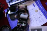
Anyway here's the (almost) finished article- the red cap covers the potentiometer which is attached with blue tac at the moment. Output is variable although I've read a 250k potentiometer is better (_http://www.krebsmicro.com/VIV283/index.html).
Total cost was:
flash - £3.21
potentiometer - 70p
knob - 94p
milk carton lid - free
A physically smaller potentiometer would have made the task easier and quicker.
The tingle may have been closer to 140-170V if it's the same as the trigger voltage (Vivitar 2800 _http://www.botzilla.com/photo/strobeVolts.html) which is why it won't be physically attached to the camera. Doing the trigger voltage modification might be next. I was lucky it the flash with the huge capactitor..
Anyway here's the (almost) finished article- the red cap covers the potentiometer which is attached with blue tac at the moment. Output is variable although I've read a 250k potentiometer is better (_http://www.krebsmicro.com/VIV283/index.html).
Total cost was:
flash - £3.21
potentiometer - 70p
knob - 94p
milk carton lid - free
A physically smaller potentiometer would have made the task easier and quicker.
Attachments


- My Satellite Setup
- Triple Dragon, Dreambox 8000, Echostar AD3000ip, TBS6522,6925,6983 PCie cards.
Gibertini 1.25m motorised dish driven by the AD3000, with either Inverto BU Quad or Norsat / XMW Ka LNBs . SMW 1.05m + 3 other dishes. Speccy: Promax HD Ranger+
- My Location
- The Flatlands of East Anglia
Glad it's all come together mate. Yes, might be worth experimenting with the potentiometer - e.g. substituting a linear one for a logarithmic one if the scaling is 'cramped' at one end.
Llew
Llew