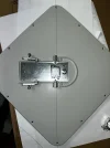
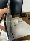
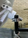
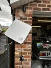
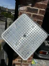
Advice Needed BSB Squarial H/V Freesat Revival Project

mydan

Member
My Satellite Setup
Historically, D-mac (Ferguson) with D2-mac mod, followed by Echostar DVB with various CAMs.
My Location
Helmshore, England
I'd like to share progress on a Squarial revival project I've been faffing with, on and off, for several weeks. The aim is to get the old Matsushita (Panasonic) version picking up the main-beam Freesat channels at 28.2°E (the 100-odd FTA channels) and, as a bonus, anything it can manage from the European beams. I've hit a brick wall near the prototype finish line and would really appreciate thoughts from anyone in the community who's got an interest or expertise.

A bit of my background - Lancashire lad, born in 1982, I grew up playing with BSB kit after it went bust. My dad and I did the film-flip for LHCP (CQ-TV issue 159) and we even bought the D2-MAC EEPROM conversion from Trac for the Ferguson receiver we were butchering. (Remember the back page of What Satellite?) The Squarial made a big impression on me as a kid and I'm sure it did for all of us who were around about the time. It'd be nice to see some out there delivering satellite signals as they themselves, for direct-to-home TV use anyway, enter their twilight years.

Fast-forward 35 years and there are Squarials on eBay. Nostalgia won over, I bought a small collection, and, as is typical for BSB it seems, even 35 years after its demise, a bloody expensive and energy sapping project was born. I have a background in software development with some mechanical and electrical engineering thrown in, but antenna design and microwave behaviour are very much "learned from reading and AI advice" territory for me.

The original film-flip mod was pointless (it only gives LHCP) and the factory fit single-probe LNB (vertical, noisy 2.5 dB, 10 GHz LO) had to go. In its place I wanted a modern 0.1–0.2 dB universal LNB. I did some searching and came across CQ-TV issue 234 which detailed a Linear-H polarity mod (which is part of this build) which changes the Squarial so it can receive horizontal polarisation from satellites, which brings a modern universal LNB somewhat within reach.

One important point: the vertical meander line and horizontal waveguide in the Squarial deliver the horizontal satellite signal to the probe in a vertical orientation. As far as I understand it, that is a fixed physical constraint, due to the shape of the waveguide and the fact there's only one vertical meander line. So the LNB <-> Receiver side needs to be clever. It can be confusing though to think no matter the polarity from the satellite, it's always delivered vertically.

We already know a universal LNB has two probes: horizontal (selected by 18 V) and vertical (selected by 13 V). In the Squarial the horizontal probe is useless because nothing gets through the waveguide. The plan is to keep the vertical probe permanently active by forcing 13 V to the LNB regardless of what the receiver sends. I'll describe the simple voltage-regulator circuit later if anyone wants it (or the project moves forward); it splits the coax so the IF passes through DC-blocking caps while a separate path feeds a regulator (with chokes and caps) to give a steady ~12–13 V. I also tap off a voltage divided 1–3 V signal before the regulator so a microcontroller can tell whether the receiver is asking for H or V.

That leads to the core idea: use an ESP32 and a small weatherproof servo to rotate the entire Squarial 90 degrees on its boresight axis. 18 V = "Home" position (BSB diamond at the bottom, natural orientation) for horizontal. 13 V = "Offset" position (diamond on its side) for vertical. Because the vertical probe is always live and the dish stays pointed at the satellite, vertical signals should appear once the rotation is correct.

I've grouped my project as it has grown into the following steps:
  1. Perform the linear-H mod
  2. Replace the factory LNB with a modern unit (modifying the casing as needed)
  3. Fabricate a new central bracket with bearings so a pole passes exactly through the geometric centre / boresight axis (think "spinning a plate on a stick")
  4. Mount the pole on a simple adjustable yoke for testing
  5. Test Home (H) and Offset (V) by hand
  6. If it works, add a second pole and servo with GT2 belt (2:1 or 3:1 ratio)
  7. Build the voltage-sensing circuit and write the microcontroller code
Here we go:

Job 1: Linear-H Mod

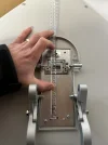
I started with a bog standard Ferguson Squarial and followed the Linear-H mod from CQ-TV Issue 234. The original pictures and instructions are a bit vague, so it took a while to get my head around it, but the process is actually straightforward once it clicks.

Remove the 12 screws from the back and lift off the front cover. Place the dish face-down on the table in its Home orientation (BSB diamond at the bottom).
IMG_0854.webp
First layer is the metal aperture plate – up-arrow and "1" on that. I also put an up arrow on the waveguide cover. Remove its four screws and set it aside. Next is the foam layer (up-arrow + "2"). Then the printed patch-array layer (up-arrow + "3"). Finally the rear foam (up-arrow + "4").
IMG_0863.webp
IMG_0866.webp
IMG_0867.webp

The metal aperture plate has 256 apertures feeding a 16×16 patch array. The original design splits the 256 patches into two 128-element groups that are deliberately 90 degrees out of phase to produce RHCP. These two groups are power-combined at the central junction while preserving the phase offset.

The mod itself: on the printed patch layer you’ll see four small metal blue strips in the corners (presumably manufacturing tabs for guillotining). Cut one out, complete with several millimetres of clear film to the side.
IMG_0868.webp

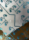
Look at the vertical meander line that feeds the waveguide. The factory slit is offset "south" – roughly centred 16 mm from the bottom of the 42 mm (outer to outer) meander line. Cut a new slit exactly in the middle (21 mm centre) with a sharp Stanley knife. Glue the "quarter-wave stub" you cut earlier directly over the original (southern) slit using clear nail polish – it doesn’t need to be electrically bonded; it's a microwave antenna. Following John's guidance, I used my wife's clear nail polish too :D

The following pictures should show the process:

Original meander line with offset slit
IMG_0942.webp

New slit at 21mm (centre of meander) and stub glued in place:
IMG_1122.webp

With the new central slit, the 90 degree phase offset disappears and horizontal signals are delivered to the vertical probe. Because the new slit must sit dead-centre in the waveguide, the whole film has to then be pulled down about 5 mm. I heated a bolt with a blowtorch and punched new mounting holes through the film.

Holes marked and punched 5mm lower:
IMG_1126.webp

Positioned on waveguide centrally:
IMG_1129.webp

Mounting holes equally punched:
IMG_1130.webp
Then everything is reassembled layer by layer in the correct orientation. That's the Linear-H mod done.

Due to picture limits, I'll need to post progress over several posts. Bear with me!
 
Job 2: LNB Replacement

The new LNB must only ever see vertical polarisation like the original, so I chose the Inverto C120 Pro flanged LNB (IDLP-SINF02, 0.2 dB). It's single-output (perfect, because the servo rotation demands means only one receiver can ever be connected) and its body is at 90 degrees to the flange, so it fits the Squarial with almost no case butchery. I got mine for £27 on eBay, the prices fluctuate by a few quid.

s-l1600.webp
Remove the single screw from the LNB cover and the five screws holding the original LNB. Keep the factory rubber seal on the Squarial waveguide.
FCB913B5-B8FB-4CA4-A45E-7E2FB136FE5B.webp

The aluminium waveguide has two alignment pips (top-left and bottom-right). I drilled them out flat so the new flange sits flush – the metal is soft enough to do by hand. Tape over the waveguide opening while drilling, then hoover out any junk.
IMG_1141.webp

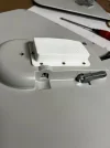
Mark a vertical and horizontal centre line through the waveguide with a Sharpie. Align the Inverto flange perfectly on those marks. The top two flange holes lined up after I opened them out a fraction; the bottom two were nowhere near. I filed the bottom corners of the soft aluminium flange until the original Squarial mounting points showed through, then used large washers and the four longer factory screws to clamp everything down metal-to-metal. The seal is still in place, so it’s solid.
IMG_1142.webp
IMG_1144.webp
IMG_1145.webp
IMG_1191.webp
IMG_1198.webp


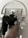
Two 90 degree F-connectors and a coupler brought the LNB output straight into the original case opening. I added a short coax tail with F-connectors to bring the cable out neatly for onward connections.
IMG_1513.webp

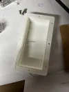
The original cover obviously no longer fitted, so I designed a simple 3D-printed shroud in OpenSCAD that screws on top and includes a 1 mm × 1 mm groove for a rubber seal. Printed at 0.2 mm layer height – rough but perfectly functional and weather-tight for now.
shroud.webp
 
LNB Completion involves, as I say, gouging out the original cover:
IMG_1204.webp

Ensuring fitment:
IMG_1208.webp

And fitting the box with seal and M3 nuts and bolts:
IMG_1271.webp

IMG_1272.webp


IMG_1276.webp
 
Job 3: New Central Bracket

The original bracket sits on 25 mm wall mounted tube and was never going to let a pole run straight through the geometric centre while allowing free rotation on bearings.

You can see by this picture, there's no way to manipulate it into something workable:
IMG_1148.webp

I went back to OpenSCAD to design my own.

Key measurement: the two main pivot bolts line up with the waveguide, which sits 5 mm south of the true geometric centre of the Squarial face (measured with taut cotton across the outer casing screws – waveguide is 19 mm × 9 mm). I decided rotation must be about the geometric centre of the Squarial so the entire face sees the same wavefront regardless of orientation. Mounting behind the waveguide would have introduced a small angular error when rotated. That’s my belief anyway and I’m happy to follow counsel.
IMG_1447 2.webp

The new bracket accepts a 25 mm pole through two 6005 bearings (47 mm OD). I also printed a GT2 toothed ring on it ready for the future belt drive.
bracket.webp

It printed well:
IMG_1500.webp
IMG_1515.webp

Replacement arms: the factory aluminium arms were too short once the new bracket was in place. I designed and printed two new arms with hex recesses so the original nuts sit captive, and the far ends accept the factory shank bolts and circlips. Several print iterations were needed to get the geometry right and the pole exiting at a true perpendicular angle to the Squarial’s face, but I’m pretty happy now that it’s as good as it’ll ever be. Note the original arm had a sleeve to find the correct elevation, this was dropped in favour a hex recess because we need the perfect perpendicular exit for the pole, and providing a tight hex recess ensures no movement.

cad arms.webp


IMG_1520.webp

IMG_1519.webp


IMG_1523.webp

IMG_1524.webp
 
Job 4: Test Mounting

I used the original wall bracket (25 mm tube pointing upwards) and a double-coupler. One side clamps the fixed mast tube; the other clamps the new Squarial pole. Both bolts are left just loose enough for hand adjustment of elevation and azimuth while testing. The whole thing behaves exactly like a circus plate spinner – the Squarial rotates freely on its own boresight axis.

IMG_1527.webp

IMG_1528.webp

IMG_1529.webp

IMG_1534.webp
 
Job 5: Testing (and the problem I'm stuck on)
I used my Zgemma H8.2H in forced 13 V mode so I could rotate the dish by hand and swap channels without building the full circuit yet.

Aligned on 28.2E and tuned to 11023/H/23000 – the box showed a solid 59 % SNR. A quick scan of all horizontal transponders gave 55 channels (a mix of SD, HD, Radio) with good lock. For a cobbled-together prototype I was chuffed; the Linear-H mod and new LNB are clearly working.
IMG_1531.webp

IMG_1535.webp

I went back to the signal finder and plumbed in 11386/H/27500, a frequency which has an equivalent V. The SNR wasn’t as great, but it enabled an easy rotation check.

Then the snag. When I rotate the Squarial 90 degrees to the Offset position I expect vertical signal to resolve and hear something on my scanner – but it doesn't and I don't. The signal fades as I move away from Home and doesn’t come back until I get back full 360 to home. However, if I rotate the entire assembly on the vertical mast about 2 mm anti-clockwise (as viewed from the front of the 25mm vertical mast – I scored reference lines) the vertical signal is found and channel searches yield another tranche of channels. Rotate back to Home and vertical drops and horizontal activates. It’s the equivalent of needing to point ~7° further east (at around 35E) to receive vertical once rotated.

The yellow score line when lined up to the score line on the aluminium clamp gets horizontal at 28.2E, when rotated "2mm anti-clockwise" I get vertical from 28.2E:
Screenshot 2026-05-13 at 19.43.06.webp

When in the green position, and at Offset rotation (for vertical) I get 75 channels
Screenshot 2026-05-13 at 19.46.23.webp

With 55 and 75, we're looking at 130 channels on a cobbled together prototype. Freesat is definitely in reach, bar this rotational issue.

I’ve ruled out a few causes which came to mind:
  • Squint: using the “Car Clinometer” app on my iPhone, I laid the phone on the Squarial’s face while on a channel and it gave an indicative gave 22–23 degree elevation. Geographic calculations at Claude (latitude, longitude, altitude, 28.2 E) after a load of horrible arctan related maths gave 22.6 degrees of elevation expected – well within the phone's tolerance. No squint.
  • Skew: rotating the dish a few degrees in Home position while listening to a signal meter showed a very shallow peak about 3 to 5 degrees anti-clockwise, but it made no meaningful difference to SNR and certainly doesn’t explain a 7 degree azimuth shift.
  • Mechanical alignment: eyeballing a corner of the Squarial against a neighbour’s brick confirmed the bracket really rotates about the boresight axis. There is a little wobble but the Squarial itself doesn't have a perfect flat face nor sides, so while it may contribute, I'm not convinced it's the issue.
  • The aperture plate and dielectric film look symmetric after the mod, with identical patch counts on each side, but I myself can't derive much from that, apart from "it looks nice."
  • I printed a bracket which didn’t have the 5mm offset, so in effect the boresight alignment was with that of the waveguide, rather than the geometry centre of the Squarial, and it made essentially no difference. In order to resolve, we’re looking at 7 degrees movement no matter what.
So I’m out of ideas.

I’m hoping someone with historic BATC experience or a deeper understanding of the Squarial's microwave design can explain why this 7 degree eastward offset appears only in the Offset position. Even "of course it does that because of X, Y, Z" would be brilliant. (Noting that Trevor Brown G8CJS did the LHCP work in Issue 149 and John G3RFL published the linear-H mod in 234 – are either still around?)

If we can crack the rotation I’ll post the ready-to-go electrical circuit and the servo/pulley mechanicals next. But I'm looking forward to the discussion. I'll post a video or two to my YouTube account and link them in here so you can see some movement.

**All the test 3D prints were done in simple cheap PLA in 0.2mm resolution. The final prints would be PETG-CF (carbon fibre re-inforced plastic) capable of extreme weather conditions.

Thank you!
 
The playlist of some of the videos I've taken is here:
 
Job 5: Testing (and the problem I'm stuck on)
I used my Zgemma H8.2H in forced 13 V mode so I could rotate the dish by hand and swap channels without building the full circuit yet.

Aligned on 28.2E and tuned to 11023/H/23000 – the box showed a solid 59 % SNR. A quick scan of all horizontal transponders gave 55 channels (a mix of SD, HD, Radio) with good lock. For a cobbled-together prototype I was chuffed; the Linear-H mod and new LNB are clearly working.
View attachment 168973

View attachment 168974

I went back to the signal finder and plumbed in 11386/H/27500, a frequency which has an equivalent V. The SNR wasn’t as great, but it enabled an easy rotation check.

Then the snag. When I rotate the Squarial 90 degrees to the Offset position I expect vertical signal to resolve and hear something on my scanner – but it doesn't and I don't. The signal fades as I move away from Home and doesn’t come back until I get back full 360 to home. However, if I rotate the entire assembly on the vertical mast about 2 mm anti-clockwise (as viewed from the front of the 25mm vertical mast – I scored reference lines) the vertical signal is found and channel searches yield another tranche of channels. Rotate back to Home and vertical drops and horizontal activates. It’s the equivalent of needing to point ~7° further east (at around 35E) to receive vertical once rotated.

The yellow score line when lined up to the score line on the aluminium clamp gets horizontal at 28.2E, when rotated "2mm anti-clockwise" I get vertical from 28.2E:
View attachment 168975

When in the green position, and at Offset rotation (for vertical) I get 75 channels
View attachment 168976

With 55 and 75, we're looking at 130 channels on a cobbled together prototype. Freesat is definitely in reach, bar this rotational issue.

I’ve ruled out a few causes which came to mind:
  • Squint: using the “Car Clinometer” app on my iPhone, I laid the phone on the Squarial’s face while on a channel and it gave an indicative gave 22–23 degree elevation. Geographic calculations at Claude (latitude, longitude, altitude, 28.2 E) after a load of horrible arctan related maths gave 22.6 degrees of elevation expected – well within the phone's tolerance. No squint.
  • Skew: rotating the dish a few degrees in Home position while listening to a signal meter showed a very shallow peak about 3 to 5 degrees anti-clockwise, but it made no meaningful difference to SNR and certainly doesn’t explain a 7 degree azimuth shift.
  • Mechanical alignment: eyeballing a corner of the Squarial against a neighbour’s brick confirmed the bracket really rotates about the boresight axis. There is a little wobble but the Squarial itself doesn't have a perfect flat face nor sides, so while it may contribute, I'm not convinced it's the issue.
  • The aperture plate and dielectric film look symmetric after the mod, with identical patch counts on each side, but I myself can't derive much from that, apart from "it looks nice."
  • I printed a bracket which didn’t have the 5mm offset, so in effect the boresight alignment was with that of the waveguide, rather than the geometry centre of the Squarial, and it made essentially no difference. In order to resolve, we’re looking at 7 degrees movement no matter what.
So I’m out of ideas.
I have no experience with this antenna, but as it is a phased array antenna, here is a theory: Internal phase shifts determine both the horizontal and vertical angle the dish focuses on, whereas the antenna layout determines polarisation.

Of course the phase-shift induced angles combine with the physical orientation you give the squarial itself.

So if you rotate the antenna, vertical angle and horizontal pointing angle are swapped, along with the polarisation and that causes your problem: The squarial is no longer pointing at the satellite. The only exception would be if the squarial behaves like a prime-focus dish, which it probably was not designed to do as people expected it to be more or less parallel with the wall.

I might be completely wrong of course. But the test would be to rotate your squarial 90 degrees to get the polarisation right and then make it point up/down and left/right differently. Or think big, and install two of them :->

Or create a solution similar to a polarmount (but different from it as the rotation serves a different purpose compared to a polarmount)


Nice work by the way!
 
The Matsushita antenna internals ( I sold them in early 1990, many were damaged in transit) , were printed to deal with a narrow group of frequencies for the Hughes Marcopolo satellite(s), the DBS band 300MHz either side of 12GHz and something the Astra 28 East bunch of birds far exceeds (both under and over) .

I would presume the LNB you have substituted for the original is handing over a raft of bouquets to your receiver, such that it cannot find the ones you are searching for through the AGC giving up. Additionally the size of the 'dish' is potentially receiving signals from other orbital slots nearby (unless perfectly aligned), owing to its size. The slot for BSB was set some 30+ years ago to avoid 2 and 3 degree separation by similar high powered locations, and of course polarity was fixed on the outdoor equipment to further prevent adjacent interference.

Unless you have a spectrum analyser to hand, try a simple attenuator using a few metres of good satellite cable (the larger diameter the better), and rescan.

If no luck then you may need to try a different LNB (Invertos are high gain/short lived devices), or start looking at cutting / stamping out the little metal squares on the reflector grid to open up the band slightly and attenuate the ones giving trouble.

Good luck.
 
The Matsushita antenna internals ( I sold them in early 1990, many were damaged in transit) , were printed to deal with a narrow group of frequencies for the Hughes Marcopolo satellite(s), the DBS band 300MHz either side of 12GHz and something the Astra 28 East bunch of birds far exceeds (both under and over) .

I would presume the LNB you have substituted for the original is handing over a raft of bouquets to your receiver, such that it cannot find the ones you are searching for through the AGC giving up. Additionally the size of the 'dish' is potentially receiving signals from other orbital slots nearby (unless perfectly aligned), owing to its size. The slot for BSB was set some 30+ years ago to avoid 2 and 3 degree separation by similar high powered locations, and of course polarity was fixed on the outdoor equipment to further prevent adjacent interference.

Unless you have a spectrum analyser to hand, try a simple attenuator using a few metres of good satellite cable (the larger diameter the better), and rescan.

If no luck then you may need to try a different LNB (Invertos are high gain/short lived devices), or start looking at cutting / stamping out the little metal squares on the reflector grid to open up the band slightly and attenuate the ones giving trouble.

Good luck.

I have messed around some more, will post an update shortly.
 
Last edited:
I like your signature, it sums this thing up perfectly.

You could be right, there are a lot of frequencies which just yield nothing, but I don't know if that's down to them being African or European slots as opposed to the Freesat offering. You're right, maybe it needs aperture faffing but I'll see if I can get away with another approach.

By cutting/stamping out the apertures, am I right in thinking make them


I have messed around some more, will post an update shortly.
I like your signature, it sums this thing up perfectly.

You could be right, there are a lot of frequencies which just yield nothing, but I don't know if that's down to them being weaker African or European slots as opposed to the Freesat offering or fundamentally out of range. I've picked up a lot of terrestrial channels of the BBC, ITV, C4 and Ch5 variety, so I'm going to cling on at least that the base Freesat offering is still doable.

You're right, maybe it needs aperture faffing but I'll see if I can get away with another approach.

By cutting/stamping out the apertures, am I right in thinking along these lines? I'd say A (bottom left) is not an option as when replicated out, would overlap with nearby apertures, and F, E, D and C have an asymmetry to them... however G and B look like sensible potentials, don't you think?Screenshot 2026-05-18 at 14.09.05.webp
 
A couple of updates to share...

Firstly, I wrongly assumed the metal aperture plate should go back as was, given the film had moved down 5mm. Again, invoking the pretty poor original instructions, it was hard to discern what the right thing to do was, however I took the front off the Squarial while it was in situ and unscrewed the plate, put back the waveguide cover and simply held it manually in front and pulled it down, and tried different orientations... and the signal meter gave higher readings when 5mm lower so I took it inside for checks.

I'm clinging on to symmetry = good, so when I held the plate 5mm lower, it brought visibility of the blue antenna array into a regular repeatable pattern, not too dissimilar to how it looks out of the factory. On reflection, it makes perfect sense it too has to be pulled down. Silly me I guess.

Further, I cut out the centre (Stanley blade is fine, it's very thin aluminium, cuts with relatively no hassle) so that it was equal.
IMG_1610.webp

And hacked the foam so it was equal too:
IMG_1611.webp
IMG_1612.webp

And with it all done, it looks spot on how it does from the factory, albeit all shifted down 5mm:
IMG_1613.webp


Next, about the 5mm offset bracket. Now it's in a correct orientation, it's now equally obvious that the bracket should be plumb central across the two main bolts and spanning the waveguide, not the geometric centre of the squarial. You can see from the dotted yellow lines I've put across, you can see how the corners of the metal aperture plate cross the waveguide, and that's the target surface area to rotate.
IMG_1613linedup.webp

So all that considered, the arrangement of the film, foam and metal looks great, is in keeping with the original philosophy, and is symmetrical vertically.

With those changes, I added 11% to the SNR and channel search found a further 50 H channels:
IMG_1616.webp


In situ:
IMG_1619.webp
New central bracket:
IMG_1617.webp

It still needs some anti-clockwise adjustment for vertical, however it no longer requires any elevation change, and it comes across, though maybe I'm imagining it, that it has all been brought "tighter."

I can see two next steps:
1. Formulate a sharp metal 'stamp' as per ChannelHopper's suggestion to punch out the aperture grid such that each of the 256 antennas gets equal input. You can see from the pictures above that the original apertures are a vertical rectangle with two triangles cut out on the left/right which does suggest a bias in the up/down vertical vs the left/right horizontal. Stamping such that there are two overlapping rectangles is a potential, or cutting out the entire shape as a Squarial diamond, as per my previous post. Those would offer equal opportunity to the antenna array, regardless of orientation.
2. You may see I've put the sleeved support brackets back on, and it was so I can manipulate the elevation. By having the Squarial pointing 'downwards' relative to the 25mm tube it is mounted on, and aligning appropriately, by the time it was rotated 90 degrees it shifted the face of the Squarial anti-clockwise towards me, introducing an Azimuth shift. My overall thinking is to potentially print the main bracket with a shorter arm, and bolt the supporting arms at an angle so that when aligned in "home", by the time it has oriented 90 degrees, the face of the dish mimics the 2mm anti-clockwise rotation.
 
Success!

To be honest I'd boxed it all up as a bad job, I hadn't progressed it in a week and the same frustrating "going around in circles" monotony had got the best of me.

Last night I'm falling asleep, the same belief that it should work on my mind, and I know I've ruled out mechanical skew and squint, so I started going over what could introduce electrical / microwave squint. We know the Squarial has seven layers:

Back cover
Aluminium backing plate with lip - 372mm x 372mm
Foam - 362mm x 362mm
Antenna array film - 362mm x 362mm
Foam - 362mm x 362mm
Aluminium aperture plate - 362mm x 362mm
Front cover

The original Linear H mod wasn't particularly well written overall but for positioning it was quite clear:
"Now by reassembling the whole thing back but making new holes through the different layers such that the new gap is in the center of the waveguide as before."

I took it that the central slit is profound, acting as a central and directing "pipe" towards the LNB.

But by moving it all down by 5mm, I considered that the only tangible change for the whole dish is that the bottom two sides of the Squarial's diamond has 0mm of perimeter between the reflecting backing plate and the top two have 10mm of perimeter, rather than 5mm all around. Could that be introducing the squint?

Recap - Note the top two sides you can see 10mm of the backing plate. On the bottom two sides there is 0mm:
IMG_1621-witharrows.webp

I went out to the garage early doors this morning and took it apart, again, and moved the foam, antenna film and aperture plate back to their factory positions. The central slit was now wholly outside of the waveguide by about 1mm. I expected nothing by the time it was reassembled, but I put it back up, got the signal meter on and adjusted to get a decent enough lock and the signal meter sounded healthy. I went to the receiver and saw it was yielding a high 60's SNR, not too far from my 70% peak when it was all 5mm lower. That's despite the slit outside of the waveguide. I fine-tuned the Squarial and got the exact same 70% SNR on 11023 / 23000 / H. I was lost for words. A channel scan got the usual BBC cohort.

I set the receiver's signal finder to 28.2E 11305 H 27500, and the signal buzzer outside made its usual noise, but it's a frequency which has a near enough equivalent at 11306 V 27500. When I rotated the dish 90, the noise from the scanner remained largely constant up to the full 90 "Offset". That was a first. Typically it dropped and disappeared shortly after leaving "Home."

I programmed one channel the receiver at 28.2E - 11305 H 27500 (Channel name = 5 Select) which has an equivalent Vertical (Channel name = Great! Romance.). Sure enough, in "Home" 5 Select comes on, rotate it 90 degrees to "Offset" and Great! Romance comes straight up on screen in its place. Drop it back to "Home" and 5 Select is back. It is bulletproof. Works absolutely perfect. Perhaps predictably, the perfect orientation is exactly mid way between my two score lines.

I was gobsmacked. Two questions which I'll need to fire at AI to even begin to comprehend... is why even with the slit outside of the waveguide does an equivalent amount of signal hit the LNB, and what is the importance of the reflecting backing plate relative to the layers sat on top?

Layers shifted the 5mm or so upwards back to the factory defaults:
IMG_1656.webpSNR 70:
IMG_1654.webp


Video of it here:


I can report > 200 channels across both polarities, however with channels both above and below the 11344/11386 ranges, it will just not pick up anything, anything at all to do with ITV. I don't know enough about this receiver to know if it's somehow excluded but I can't get a lock on those manual frequencies with the correct SR/FEC/PSK.

With the full BBC, C4, C5 and a range of other services coming up, and supposedly ITV on a main Freesat UK beam, it's just shy of worthy of continuation :(. It may be that 11386 on both polarities at - 8PSK - 27500 is simply too much, but I'll keep persevering a bit longer.

I'm just glad the original belief held true, both H and V are a potential with a simple 90 degree swap!
 
Interesting plot twist - my dad recommended I put a factory film and aperture plate back just to see how it performs. Due to the order of execution I'd done the Linear H mod first, and had never tried the original config with the new LNB attached. I have a few Squarial's in the garage so I had plenty to test with.

In short, amazing.

Whatever problem the original Linear H mod was trying to solve (perhaps it was to accommodate the original LNB or signals as they were at the time), it has a destructive effect on the Squarial far in excess of any loss as a result of being designed with 90 degree offset in mind.

Results on SNR:
First: My original implementation of the Linear H mod (without the aperture plate moved down 5mm) but boresight bracket 5mm offset yielded 56%, give or take.
The second iteration which was to move the aperture plate down 5mm and have a centrally aligned boresight bracket I got 70% SNR but 90 degree rotation required significant azimuth shift to resolve signal.
The third iteration which was to move the aperture plate and film back to the factory position retained a 70% SNR but the 90 degree rotation was much more forgiving. (Something I can improve more with tighter printed brackets, removing any final small lateral+longitudinal movement.)
The fourth iteration - original film and aperture plate 80% SNR and the best haul of channels yet, including finally some ITVs which admittedly, were struggling, but it's continued progress :)
IMG_1779.webp

As I'd used clear nail polish to attach the stub, I gave some thought to "undoing" the Linear H mod (as I hate to think of any Squarial ending up at the tip) and so I took to it with nail polish remover and sure enough, the stub came off fine and cleared up nicely. I simply re-positioned the stub over my central slit and re-assembled. It too gets 80% SNR (despite the now obvious hackery to the aperture plate, especially in the centre where I've tried various things to improve its luck.) so there's potential for further gains there too, but we're approaching the limit I'd say.

IMG_1775.webp
IMG_1776.webp
IMG_1782.webp

I'm going to see the project through to completion, but I'm going on holiday for a couple of weeks. I have built the 12V circuit, I've coded up the ESP32 microcontroller to rotate the servo and I've built the servo circuit, I'm just waiting on a GT2 belt and some final wire to see it in action.

You should be able to see the intention in this picture:
IMG_1785.webp
I designed a servo mount which sits on the same 25mm tubing, but allows for the servo to be bolted to it. The steel tube is glued to the mount. Because it can twist within the double coupler, the drive pulley and Squarial bracket (which is exactly 2:1) has centres of 10cm up to 17cm, meaning there is plenty of scope for any size GT2 belt around the 35-45cm range, and plenty of scope to loosen off, fit the belt, and twist it until the belt is tight. It should work well.
Screenshot 2026-05-28 at 12.34.09.webp

The 2:1 drive pulley was also done in OpenSCAD, sporting the GT2 tooth profile, and the 25T servo shaft from the £6.50 cheap test servo I got from Amazon.
Screenshot 2026-05-28 at 12.37.22.webp

So, it'll go quiet for a few weeks while I finish it up but I'll let you know the final results and share the two circuit schematics when I'm assured they're where they need to be.
 
Great results with the improved SNR. Enjoy your holiday and I'll look forward to an update when you get a chance.
 
Top marks all round - excellent documentation, modification & fabrication work :Y .
 
Complete, for now, but I'll keep trying for ITV in my spare time.

The Linear-H mod has made a return and I'll advocate for it. There is merit in it after all as long as it is done right. Whilst the original RCHP film and aperture plate a couple of weeks ago got 80% on a fine sunny day, I had concerns about cross polarisation noise. In pursuit of ITV, the two transponders in question - 11344 and 11386 have both H and V on the same frequency. On 11023 (my booming BBC channel) there is only H. On the RCHP variant, rotating the Squarial retained signal near enough through 360 degrees. Don't get me wrong, it dropped, and it went out between 80 and 100 degrees and 260 and 280 degrees, but the rest it did resolve signal. In effect, it has a massive rotational arc where it can mop up signal. This happens because the 5mm offset slit in the original design acts as a quadrature (90 degree) phase splitter. When a single linear wave (such as 11023 H) hits the array, the internal feed network splits its energy into two paths, delays one path by 90 degrees relative to the other, and launches them into the waveguide transition. Because the antenna is synthesising a circularly polarised output internally, the vector entering the waveguide rotates. As the Squarial is spun, the phase angle of the vector is rotated, but it must be that because there is no competing signal on that frequency, the "WR75" waveguide always manages to scoop up a massive chunk of the propagating energy, especially when coupled with a modern 0.2dB LNB. It only drops out when the rotation forces the synthesised vector to align perfectly with the non-propagating wide wall of the waveguide. (Ala the 90 and 180 positions.)

So on something like 11386, the unaltered Squarial has a massive acceptance arc for both polarisations, so the Squarial can aggressively 'drink' from both the H and V hosepipes at the same time. So I'm saying (without the education to underpin it) that there is significant cross contamination. As H and V are completely different data streams carrying different ITV regions, mixing them with a 90 degree phase offset creates an un-decodable, mess of co-channel interference. Spinning the dish on its boresight axis changes the relative amplitudes of H and V entering the mixer, but the 90 degree phase-shifting mechanism of the offset slit ensures they are always cross-contaminating each other.

So, going back to John's Linear-H mod, I'm of the opinion that a central slit is not necessary and that the internals should not be lowered 5mm down. Lowering 5mm relative to the backplate and waveguide introduces 7 degrees of squint - easily corrected for elevation but breaks when rotated for azimuth, resulting in the 7 degree Eastwards shift. The replacement slit is utterly pointless. In the original design it was a quadrature phase separator, and its sole job was to act as a barrier that forced the left hand of the array to be 90 degrees out of phase with the right, synthesising RHCP, completely not needed for a linear system. By bridging the entire meander line we get a forced 0 degree phase difference ~ and crucially, it then achieves massive cross-polarisation discrimination. You'll recall in my first posts that the signal died with a few degrees of shift. I took it as bad, but actually it is good. It means it is finely tuned and 'focused.' As for bridging the gap, I decided that rather than using the entire stub (1cm, give or take), I would use as little as possible to bridge the gap. I cut a 2mm slice from the stub and once again, with nail varnish, bridged the gap. This means there is minimal overlap and the meander retains as much original behaviour as possible. I also didn't allow nail varnish between the stub and meander, only in effect gluing the clear film to the side. In short, it worked GREAT. Considering today is a really dark cloudy day, I got 82% SNR on 11023, whereas I "only" got 80% on a beautiful blue sky day a couple of weeks ago. I suspect 86%-88% is possible in perfect conditions. And crucially, there is H + V discrimination. It's a much easier mod, literally cut the stub out, shape it to 2mm, glue it and reassemble. No burning replacement holes or ensuring alignment or butchering the metal aperture plate. On the test bench now is an RHCP film with gap bridged with a 2mm stub, and an original non-butchered aperture plate, all in the original factory positions. I'm saying for now that it's as good as it gets.

IMG_1996.webp


Moving the Squarial...
The GT2 belt came, and I rough re-printed the main Squarial bracket with a new GT2 tooth profile (the original teeth were too small, so it skipped teeth on first run) and tightened the inner width so it was snug on the Squarial, removing any final lateral or longitudinal movement:
A590975F-CEBF-43CE-9FF1-04AC1C86B187.webp

Circuits:
Two circuits are required.

1. 12V LNB Regulator with AC Bypass:
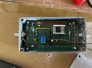
This circuit is encased in an aluminium die-cast box to prevent interference. It sits in between the LNB and receiver. The receiver "output" (or input if you will) is split two ways. IF goes via two DC blocking capacitors and straight to the output. DC goes via IF blocking chokes where it is subject to a 12V voltage regulator and re-connected to the output. The end result is preserved IF and no matter what comes out of the receiver (18V or 13V), 12V is always delivered to the LNB, keeping the vertical probe active. Further, prior to the regulator, a simple two resistor voltage divider is used to ensure that we have a ~1V - ~3V signal wire which we can use in our second circuit in order to move the dish.

Schematic:
IF Circuit Schematic.webp


PCB layout I replicated on prototype board:
IF Circuit.webp


Completed circuit:
IMG_1707.webp


2. Servo Controller:
This circuit has a single 12V power source in order to power both the microcontroller which will drive the servo, and power the motor. I chose a 6.5V switched regulator for the servo (for speed and torque) and 5V linear for the ESP32. The signal from the first circuit is 3.3V protected with two diodes (so if one resistor blows, it won't take out the ESP32). There is a pointless jumper for 270 degree servos (in reality, the code needs recompiling with PWM values suitable for any motor purchased, but I've left it in the schematic.). There is another jumper to force 'home' - perfect for calibration. It ensures the belt can be strapped around the Squarial and motor during set up so home is indeed home with the BSB logo at the bottom. The third jumper is direction. By default it will rotate anti-clockwise 90 degrees, but with the jumper in place bringing the pull-up to ground, it will rotate clockwise. I figured some houses or folk will find it more suitable to do a cable run one way rather than the other. The switch just gives flexibility.

Servo Schematic:
ServoSchematic.webp

Servo Circuit I built:
ServoCircuit.webp


Servo Circuit Built:
IMG_2006.webp

The servo controller code I'll clean up and post tomorrow, it includes ramp-up and ramp-down code, including mid-flight ramp-down and ramp-up. Think browsing through channels quick, sudden jolts won't be healthy for the belt, brackets or mechanisms, so on change of voltage in mid flight for example, it will slow back to zero, then accelerate the other way. All this happens quick, the Squarial rotates in about 1/3 of a second. For channel searching, I still found it more palatable to search all V channels first, and all H channels second, to limit quick rotations, however it would take it all day long.

So, despite all that, I've reached pinnacle signal strength so far, it discerns between H and V, and rotating between channels is great, but ITV remains elusive. I can only put it down to the amount of bandwidth / signal required for 8 PSK / 27500, and I have had sight of ITV on a perfect day... Just something tells me something obvious is missing.

I'll post the 3D models online, or if someone has an interest in building their own Squarial project, feel free to link in and I'll share with you or we can work out printing some brackets and postage. I have about 30 Squarials in my garage... They're on eBay if anyone wants to bring one to life. I'm making as much as this open source as realistically possible, and I've shared the journey. I'd be pretty happy if someone else took the reigns too and did their own discovery ~ someone more intelligent than I :D

I'll post some videos in a moment, it's quite a ridiculous project, but it proves the little short lived Squarial from 1990 can actually deliver DVB-S2 on modern linear signals. And that's cool.
 

Attachments

  • IF Circuit Schematic.webp
    IF Circuit Schematic.webp
    74.5 KB · Views: 6
Initial daft rotation test during channel search -
It works! -
Circuit walkthrough -
 
This is a really interesting project, thanks for sharing it with us @mydan :)

The troubles with ITV are curious, at the signal levels you're receiving the BBC and others with, there should be plenty of margin, and the modulation parameters are even slightly more robust than the BBC transponders on at least some of the ITV ones (FEC 2/3 instead of 3/4).

I wonder how the setup would do on 19.2°E or even 13°E. :D
 
Back
Top