Bullseye Vs SMW Q-PLL Ku LNB Comparison

s-band

Member
My Satellite Setup
1.5m IRTE PF, Invacom SNF-031, TBS6983,
Various L, S, C, X & Ka bits. 1.2m S/X/Ku/Ka Prodelin on Az-El (being refurbished), 1.8m Precision PF with Bullseye Ku LNB or various C & X bits
My Location
Essex
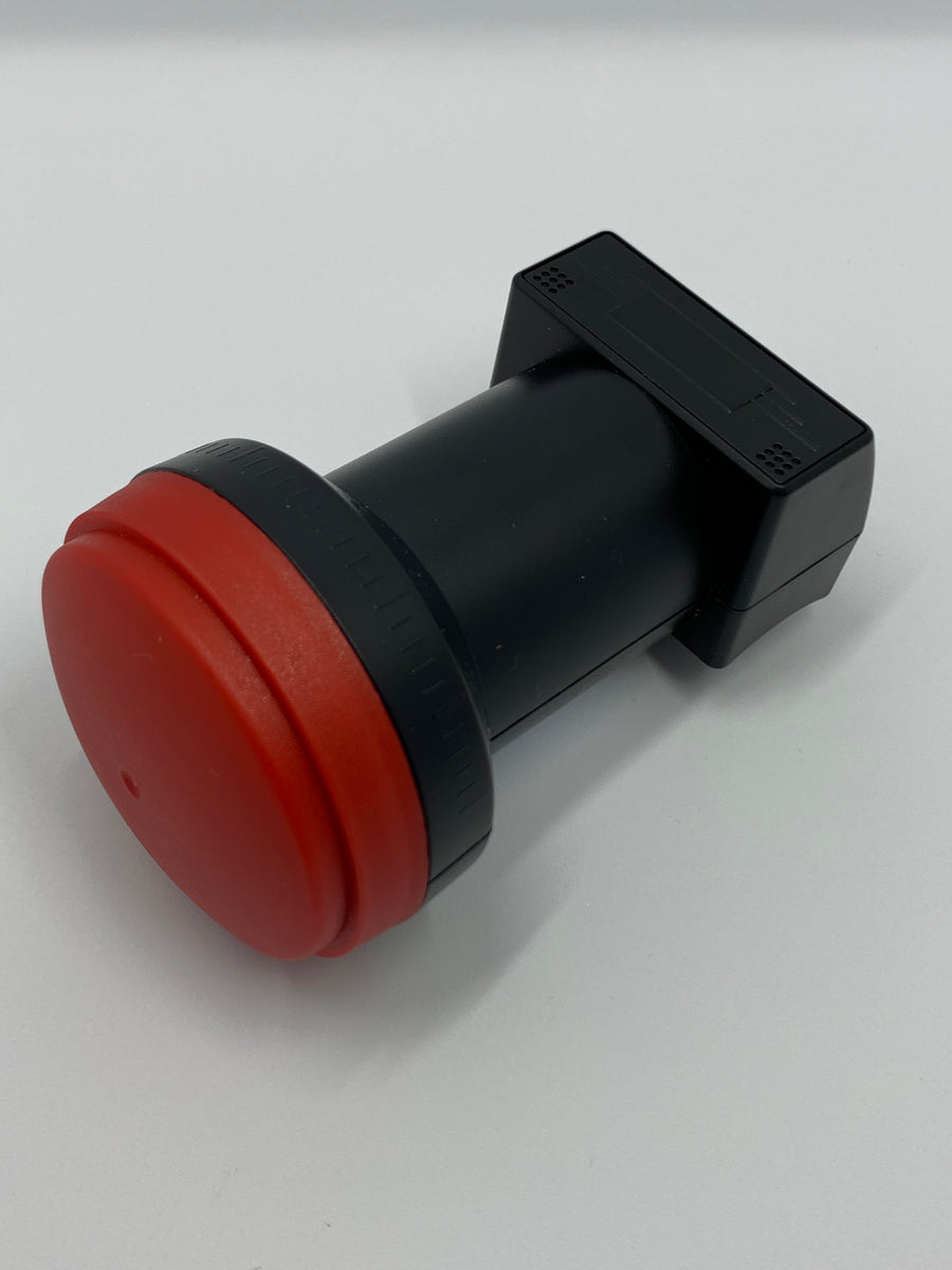
I carried out some tests to compare a Bullseye LNBF with a SMW Q-PLL Type C on a 1.8m PF dish.
SMW_qpll_C_1.8s.jpg SMW Q-PLL Type C on IRTE C120 adapter
Bullseye-on-dish-s.jpgBullseye LNBF with feed removed fitted to C120 flange from Invacon LNB

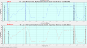
The plots here used Crazyscan's blind scan 1 with 2MHz steps. This gives more repeatable results than BS2 but doesn't catch all signals. I would normally compare systems using Sun noise but the tracking dish is out of use at the moment. Notes:
  • Cloud cover changes resulted in 0.5dB variations, maybe more.
  • 7E chosen as it was of interest at the time
  • 10804 and 10845H give random values sometimes
  • Skew set by nulling beacons. SMW had >32dB X polar rejection and Bullseye <27dB
  • 10720H varied by the most with varying cloud (to be expected)
  • Number of feeds varied through day
  • Might be better to do 7W as that has most low level signals
  • High SNR signals give poor indication of differences as 1dB RF change results in <<1dB SNR change when > about 15dB SNR.
  • BS1 used with 2 MHz steps, BS1 & BS2 scans saved as .ini
7E_V_Low_BS1_SMW-bull.png 7E_V_High_BS1_SMW-bull.png
7E_H_Low_BS1_SMW-top_bull_bottom.png 7E_H_High_BS1_SMW-top_bull_bottom.png
 
Yes, the Bulls Eye is very good!

Thanks for the detailed test
 
Do you have a link for the ku lnb
 
Cool

what does 10HZ mean ?
is the red / green port both the same ?
is this the new inverto black ultra?
 
On non modified LNBFs I found the Fracarro UX-TW series slightly outperformed the Bullseye, but it was close.
 
Cool

what does 10HZ mean ?
is the red / green port both the same ?
is this the new inverto black ultra?
From link:
  • Frequency stability within 10 kHz in normal outdoor environment
  • 25 MHz output reference available on secondary F-connector (red)
IBU? I was never a fan of these but others rate them highly.
 
Whats the second f connector for SDR?
 
for various applications requiring a stable frequency/reference
 
Here's another picture of my flanged Bulls Eye LNB. I extended the waveguide and adjusted it precisely so that there are no transitions or edges. Then shortened to lambda 1/2 and glued the self-made flange. This works very well.
 

Attachments

  • Bulls Eye_1.JPG
    Bulls Eye_1.JPG
    94.3 KB · Views: 82
  • Bulls Eye_2.JPG
    Bulls Eye_2.JPG
    138.4 KB · Views: 82
Here's another picture of my flanged Bulls Eye LNB. I extended the waveguide and adjusted it precisely so that there are no transitions or edges. Then shortened to lambda 1/2 and glued the self-made flange. This works very well.


Nice work :Y.
 
Hi! Can anyone tell us if bulls eye lnb gets better results than IBU or golden media +?
Has there been any comparison test between them?
 
Here's another picture of my flanged Bulls Eye LNB. I extended the waveguide and adjusted it precisely so that there are no transitions or edges. Then shortened to lambda 1/2 and glued the self-made flange. This works very well.
Where is the lambda/2 dimension, please?
 
After calculating the waveguide irradiator with D = 18.3 mm, the average Ku length was found to be Lo = 25.8 mm
Lc = 31.2 mm
Lu = 23.9 mm
Lg = 45.8 mm
The height of the probe in the waveguide Lo / 4 = 6.4 mm
Distance from the probe to the rear wall of the waveguide (short circuit or reflector) Lg / 4 = 11.4 mm
So we have found that a pin of 6.4 mm length should be at a distance of 11.4 mm from the empty wall of the waveguide. The coefficient of reflection from it is -1, so the reflected wave returns to the probe in half a period and sums in phase with the wave incident on it. The signal at the output of the illuminator will be maximum.
And now let's look into the real waveguide:

The thickness of the probes is 1.2 mm, so from the axis of the lower probe to the deaf end of the waveguide is 6.5 mm, the minimum distance from the probe to the reflector is 5.9 mm, the maximum distance is 7.1 mm. At least one of these figures is close to 11.4 mm?
These figures correspond to a quarter length and 26, 24.5 and 28.4 mm respectively or approximately middle, outer and upper Ku range.

Let's see at what distance from the open end of the waveguide the receiving probe should be. Lg / 2 = 22.9 mm.
And indeed - 13.3 + 0.6 = 13.9 mm, which corresponds to half the wavelength at a frequency of 10.8 GHz in free space.

Contrary to the prevailing misconception, the height for the best adaptation of the receiving probe to the irradiation device of its (probe) must therefore be
Lambda min / 4
The distance from the probe to the boundary of the irradiator / waveguide must be a multiple
Lambda aver / 2
The distance from the probe to the electrical wall of the waveguide must be
Lambda aver / 4
Where lambda aver is the average wavelength in free space

The waveguide dimension is always different for different LNBs and must be included in the calculation!!
 
After calculating the waveguide irradiator with D = 18.3 mm, the average Ku length was found to be Lo = 25.8 mm
Lc = 31.2 mm
Lu = 23.9 mm
Lg = 45.8 mm
The height of the probe in the waveguide Lo / 4 = 6.4 mm
Distance from the probe to the rear wall of the waveguide (short circuit or reflector) Lg / 4 = 11.4 mm
So we have found that a pin of 6.4 mm length should be at a distance of 11.4 mm from the empty wall of the waveguide. The coefficient of reflection from it is -1, so the reflected wave returns to the probe in half a period and sums in phase with the wave incident on it. The signal at the output of the illuminator will be maximum.
And now let's look into the real waveguide:

The thickness of the probes is 1.2 mm, so from the axis of the lower probe to the deaf end of the waveguide is 6.5 mm, the minimum distance from the probe to the reflector is 5.9 mm, the maximum distance is 7.1 mm. At least one of these figures is close to 11.4 mm?
These figures correspond to a quarter length and 26, 24.5 and 28.4 mm respectively or approximately middle, outer and upper Ku range.

Let's see at what distance from the open end of the waveguide the receiving probe should be. Lg / 2 = 22.9 mm.
And indeed - 13.3 + 0.6 = 13.9 mm, which corresponds to half the wavelength at a frequency of 10.8 GHz in free space.

Contrary to the prevailing misconception, the height for the best adaptation of the receiving probe to the irradiation device of its (probe) must therefore be
Lambda min / 4
The distance from the probe to the boundary of the irradiator / waveguide must be a multiple
Lambda aver / 2
The distance from the probe to the electrical wall of the waveguide must be
Lambda aver / 4
Where lambda aver is the average wavelength in free space

The waveguide dimension is always different for different LNBs and must be included in the calculation!!
I think I mentioned a while ago the waveguide can easily be 'sleeved' with the remains of a can of cider, or lager (though I rarely drink the stuff if it is not bottled).

And some other piccys of a C120 flange from the other side of the pond. Dimensions were supplied many years ago.


Cheers !
 

Attachments

  • 20240909_074140[1].jpg
    20240909_074140[1].jpg
    1.8 MB · Views: 50
  • 20240909_074132[1].jpg
    20240909_074132[1].jpg
    845.1 KB · Views: 53
Warning: Beware of swarf

I decided to modify the Bullseye LNB shown here to use an external reference. Once opened, I could see a lot of swarf on the PCB. It had mainly collected on the sticky remnants of flux. It had the potential to mess the thing up completely and was quite close to having done so. I suspect it may have been forced into the electronics cavity by my use of an air line to clean it after hacking the feed off.
 
Last edited:
Back
Top