KA Band C with a modded Inverto LNB

Llew

cerca trova...
Staff member
My Satellite Setup
Triple Dragon, Dreambox 8000, Echostar AD3000ip, TBS6522,6925,6983 PCie cards.
Gibertini 1.25m motorised dish driven by the AD3000, with either Inverto BU Quad or Norsat / XMW Ka LNBs . SMW 1.05m + 3 other dishes. Speccy: Promax HD Ranger+
My Location
The Flatlands of East Anglia
Another day, another Inverto...

I needed a spare feedhorn for my KA LNBs, and as the one removed from the Inverto KA LNBF I had outperforms the Norsat FD1000 on them, I aquired another one with the intention of depriving that of said feedhorn.

Before I do that, I thought I'd experiment with trying different DRO pucks in the LNB to see if it's capable of working to a different KA band. In a word, yes.

In my opinion (and it may be common knowlege, although I hadn't expected it to be so), the DRO in the Inverto uses a 10.6 GHz KU puck, and the Inverto operates using its second harmonic to oscillate at 21.2 GHz - I don't see any frequency doubler before the mixer in the circuit, but I stand to be corrected.

This was proven by removing the original puck and substituted it for a 10.6 GHz KU one, scavenged from an old KU LNB. The results were the same on KA-Sat 9a as with the original DRO puck.

Now for some fun. I then re-substituted the puck for a 9.75 GHz KU one, to see if the LNB would work in the KA C Band. I adjusted the DRO screw to bring the oscillator down to below the band, rather than the oscillator working above band, as with the normal Inverto's inverted spectrum output.

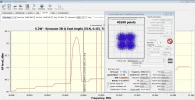
Now with the oscillator tuned to 19.035 GHz, I went to 12W to see if I could receive the carriers at 20307V and 20730V. No problem, good signals at 5.8dB and 9.1 dB. Allowing for the -3dB drop using a circular LNB, results seem promising.

There are some inclined sats in this band, as Vipersan and myself have received with the Hughes LNB, that could be worth investigating later.

A point worth making regarding changing DRO pucks - I found that rather than tediously glueing and unglueing them from the circuit board, I used Sellotape double-sided tape. Sticks firmly and is easily removed. Glueing the puck properly is an option if I decide to use this LNB purely for the KA C Band, but at present this is just for testing the capability of the LNB.
 

Attachments

  • Modded Inverto at 12W.webp
    Modded Inverto at 12W.webp
    189 KB · Views: 129
Impressive! I'm looking at my Inverto Ka LNB now, but I haven't plucked up the courage to take it apart.
My first improvement is likely to be based on a comment made by VS about removing the plastic cover giving an extra 0.5dB - is there any easy way of removing the cover without damaging it? (I'd rather ask then try and it get it wrong).
I am also curious as to how you are measuring the frequency of the oscillator once you've adjusted it (to get an idea of what tools would be required)
 
Impressive! I'm looking at my Inverto Ka LNB now, but I haven't plucked up the courage to take it apart.
My first improvement is likely to be based on a comment made by VS about removing the plastic cover giving an extra 0.5dB - is there any easy way of removing the cover without damaging it? (I'd rather ask then try and it get it wrong).
I am also curious as to how you are measuring the frequency of the oscillator once you've adjusted it (to get an idea of what tools would be required)
Vipersan's tip - just immerse the LNB's cap in a bowl of hot water for five minutes and it should be able to be prised off easily enough. Don't drop it right into the bowl though!

I used a spectrum analyser (my Promax) to adjust the DRO screw so that the carriers fell within the analyser's IF band. If you don't have an analyser, as a rough guide, the screw stands proud of the DRO cover by about 2mm.

I then went to my PC card's Crazyscan analyser and checked what the carrier frequencies were displaying. They were only 35 MHz out from the correct frequencies, so it was just a matter of correcting Crazyscan's LO, which I entered as 19000 MHz at first. I adjusted Crazyscan's LO by 35MHz (to 19035 GHz) to obtain the correct frequency readout.
 
Impressive! I'm looking at my Inverto Ka LNB now, but I haven't plucked up the courage to take it apart.
My first improvement is likely to be based on a comment made by VS about removing the plastic cover giving an extra 0.5dB - is there any easy way of removing the cover without damaging it? (I'd rather ask then try and it get it wrong).
I am also curious as to how you are measuring the frequency of the oscillator once you've adjusted it (to get an idea of what tools would be required)
Re removing the cover without damage is easy ..
Boil a kettle and pour about an inch of boiling water into a bowl ...
then dip the cover end of the lnb in the water for about 30 seconds ..
The lift it out and with a butter knife and a tea towel ease on edge of the cap and flip it off ..
If it refuses to budge ...just repeat until it comes off..

Llew ..
Excellent work buddy ..
Much to play with once the elevation project is complete.
;)
Beat me to it Llew ..
I can't type quick enough..
lol
 
OK, stretching the Inverto mod a bit, but I can lock the 5.2W carrier at 20880H after inserting a small dielectric plate into the feedhorn. Possibly getting towards the receivable end of Band C now with this mod. Not sure if there's anything worth trying for further up the frequency band?
 

Attachments

  • Modded Inverto 5.2W.webp
    Modded Inverto 5.2W.webp
    184.4 KB · Views: 89
  • 5.2W with Inverto.webp
    5.2W with Inverto.webp
    78 KB · Views: 69
Another day, another Inverto...

I needed a spare feedhorn for my KA LNBs, and as the one removed from the Inverto KA LNBF I had outperforms the Norsat FD1000 on them, I aquired another one with the intention of depriving that of said feedhorn.

Before I do that, I thought I'd experiment with trying different DRO pucks in the LNB to see if it's capable of working to a different KA band. In a word, yes.

In my opinion (and it may be common knowlege, although I hadn't expected it to be so), the DRO in the Inverto uses a 10.6 GHz KU puck, and the Inverto operates using its second harmonic to oscillate at 21.2 GHz - I don't see any frequency doubler before the mixer in the circuit, but I stand to be corrected.

This was proven by removing the original puck and substituted it for a 10.6 GHz KU one, scavenged from an old KU LNB. The results were the same on KA-Sat 9a as with the original DRO puck.

Now for some fun. I then re-substituted the puck for a 9.75 GHz KU one, to see if the LNB would work in the KA C Band. I adjusted the DRO screw to bring the oscillator down to below the band, rather than the oscillator working above band, as with the normal Inverto's inverted spectrum output.

Now with the oscillator tuned to 19.035 GHz, I went to 12W to see if I could receive the carriers at 20307V and 20730V. No problem, good signals at 5.8dB and 9.1 dB. Allowing for the -3dB drop using a circular LNB, results seem promising.

There are some inclined sats in this band, as Vipersan and myself have received with the Hughes LNB, that could be worth investigating later.

A point worth making regarding changing DRO pucks - I found that rather than tediously glueing and unglueing them from the circuit board, I used Sellotape double-sided tape. Sticks firmly and is easily removed. Glueing the puck properly is an option if I decide to use this LNB purely for the KA C Band, but at present this is just for testing the capability of the LNB.

Do you mean all you had to do was turn the screw down?
 
Do you mean all you had to do was turn the screw down?
Screwed down, but not fully at present. It'll go further in to increase the Band C range, but I haven't found any transmissions further up (yet).

As I mentioned, the LNB is now acting as a normal Ka LNB rather than its originally intended Ka Inverto LNB, because it's now flipped its spectrum output to above the LO rather than below, like a normal Ka LNB - so you use the Ka Band option in Crazyscan.

9.750 GHz DRO puck now superglued on, and a dielectric strip 20mm x 12mm cut from an old (ahem) Sky card and inserted into the feedhorn at more or less 45 degrees to the horizontal for max signal.


5.2W Ka.webp
 
...a dielectric strip 20mm x 12mm cut from an old (ahem) Sky card...
Naughty, naughty, I don't think that was yours to cut up. What if they want it back? ;) :p
 
Naughty, naughty, I don't think that was yours to cut up. What if they want it back? ;) :p
Like the proverbial parrot, it's expired, dead, snuffed it :eek:
They can have all my other expired ones too, including my current worker; I hardly use it these days - I may well be cancelling my subscription soon.
 
Like the proverbial parrot, it's expired, dead, snuffed it :eek:
They can have all my other expired ones too, including my current worker; I hardly use it these days - I may well be cancelling my subscription soon.
Canal Digital in Finland used to send you an envelope and a little plastic case to put your cancelled card in. I don't think they still do it though as I've got a couple of old cards that they didn't want back.
 
Hi all,

I'm using an Inverto LNB here for general Ka-band reception. It has been modified to allow an external LO input which can be generated with frequency precision. As Llew says in the initial post, the original DRO oscillator operates at 1/2 the wanted frequency, due to a sub harmonic mixer being used. This means that its possible to feed in 10.6GHz for normal 'Saorsat' operation. The other modification was to strip out the pair of bandpass filters after the LNA stages, this is needed to give good wideband performance although at the expense of image noise. Provided the LO is kept above the wanted frequency it seems to perform very well indeed. It is also possible to stick dielectric material over the top of the existing bandpass filters, 'clean' PTFE or duroid material is good, you can usually shift the frequency a few hundred MHz using this method.

Attached is a pic of the internals of the modified LNB;

inverto_extLO.webp

Not much to see on the other side of the casting except the SMA input for the LO/2.
 
A nice mod Paul.

I don't have a suitable external frequency source available to inject, so I'll have to make do with adjusting the DRO.

I have used a piece of Sellotape foam strip on the filters mentioned, which seemed to increase signals, but your idea with copper strip may be worth trying.
Thanks.
 
Back
Top