Marantz SR4200 amp issue

Captain Jack

Retired human
My Satellite Setup
See signature
My Location
North Somerset
I have an old Marantz SR4200 amp, which has been a good workhorse except for one small thing.

After switching on, the digital/optical input stops working for about 30 seconds after 2 mins. We can kick this back into action by turning the unit off (with remote) for a few seconds and back on - or wait 30 seconds. After this, it works fine forever.

The obvious workaround is to keep it switch on but electrickery costs £ and we don't want it on all night.

Any obvious solutions? Maybe PSU caps need replacing? I haven't looked inside yet.
 
If it where the power supply caps it would not recover and work fine forever.

Without a schematic it would be hard to deduce the possible problem area, I will try a look up for one.
 
OK, I have found this.

Code:
https://www.manualslib.com/manual/720887/Marantz-Sr4200.html?page=3#manual

If you look at page 8 you will find the input PCB schematic, (sorry it's poor quality) in the bottom left of the schematic you will see two IC chips use dfor the digital/optical inputs, one is an input buffer,(IC11) the other is the main input digital decoder, (IC12) on this chip there is a crystal oscillator, (X101) if this has gone into an intermittent startup stage it may need replacing, (seen it happen) this xtal** may be on the verge of its outside oscillating range due to age, you kicking it around by cycling the power may just keep it going.

**xtal, short for crystal oscillator.

It also could be IC12 it's self going bad, or maybe the buffer IC11, if you look on the xtal circuit there is a feed to other parts of the board,(labeled OSC) but due to the poor quality of the page it's hard to tell where the feed from the xtal is going.

The only way to trouble shoot this stage is with a frequency counter and an oscilloscope.
 
OK, I have found this.

Code:
https://www.manualslib.com/manual/720887/Marantz-Sr4200.html?page=3#manual

If you look at page 8 you will find the input PCB schematic, (sorry it's poor quality) in the bottom left of the schematic you will see two IC chips use dfor the digital/optical inputs, one is an input buffer,(IC11) the other is the main input digital decoder, (IC12) on this chip there is a crystal oscillator, (X101) if this has gone into an intermittent startup stage it may need replacing, (seen it happen) this xtal** may be on the verge of its outside oscillating range due to age, you kicking it around by cycling the power may just keep it going.

**xtal, short for crystal oscillator.

It also could be IC12 it's self going bad, or maybe the buffer IC11, if you look on the xtal circuit there is a feed to other parts of the board,(labeled OSC) but due to the poor quality of the page it's hard to tell where the feed from the xtal is going.

The only way to trouble shoot this stage is with a frequency counter and an oscilloscope.
He can try warming the Xtal to diagnose :)
 
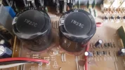
Welp, I never got around to this until now. I am certainly not going to start messing with ICs but I might replace the crystal and the two huge capacitors - C915 and C916. Both are bulging, so it would only be a matter of time before they pop.

20180730_142537.webp

I am sure a huge layer of dust from 15 years of constant use doesn't help...

As I'll be selling it, and it's not really worth all that much, I won't spend more time than this...
 
Welp, I never got around to this until now. I am certainly not going to start messing with ICs but I might replace the crystal and the two huge capacitors - C915 and C916. Both are bulging, so it would only be a matter of time before they pop.

View attachment 118966

I am sure a huge layer of dust from 15 years of constant use doesn't help...

As I'll be selling it, and it's not really worth all that much, I won't spend more time than this...
They look fine to me, they are either filter caps or reservoir caps.
 
Back
Top