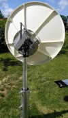
STEP #3- attach 2 metal angles between PM and the dish. Find such a position of the dish that it goes out of edgy positions very easy.
Forgive me if I am being thick, but can you explain to me why this would work?
I have no mechanical engineering training or the like.
Just vague rememberings of high-school physics, and my "in-head 3D modeling" and intuition.
The latter two keep telling me that you gain little (well, nothing) from shifting the dish/weight down the polar axis.
My conclusion:
As far as I can figure it out, the amount of work (energy) required to move the dish on the axis of inclination (i.e. the axis of rotation of the polar mount) from one point to another on the arc should be the same, as it is about tipping fixed weight around the same central axis (which in principle can extend infinitely up or down).
The position on this axis the physical weight is attached only influences the load on the bearings in the points where the axis is actually mechanically hinged. Not the amount of work required to move dish.
Reasoning:
The work required to move the dish roughly speaking affects three components:
[gravity pulling the weight of the dish] + [inertia of accelerating the weight of the dish] + [mechanical friction of bearings & hinges]
Adding counter-weights to balance the dish on the axis of movement removes (as far as possible) the pure-gravity component of the resistance of the movement, whereas inertia due to mass-acceleration (of dish and counterweight) and bearing friction remains (and may actually increase due to the added weight).
The gravity induced component, as I see it, can only be lessened primarily by distributing the weight evenly (counter-weights), or secondarily by moving the actual dish face as close to the axis of inclination as mechanically possible.
Moving the dish closer to the axis of inclination is, again as I see it, why PF dishes are easier to drive than offset dishes, where the weight is further from the axis due to the necessary declination of the offset dish (due to the offset).
In fact, it is even possible to find such a position that PM will turn antenna to central stage without any power applied. Agree, it looks unusual and even strange, but it works.
Following the logic above, I find it hard to see how this can be achieved without counterweights that would not only balance the weigth of the dish, but actually weigh *more* than the dish. This would allow the whole thing to swing back into position if power was removed from system.
The ideal way to obtain either equilibrium, or even "return-to-center" behaviour would be if you moved the dish not just down, but also backwards.
If you can align the centre of gravity of the complete dish-assembly with the polar axis of the mount, then you can equilbirum. Move it even further back, and you get return-to-zero.
Mechanically, this would require you to "bend" your L-shaped beams to accomodate the dish beow or above the mechnical hinges.
It would look rather weird, though, and would required substantial bushings. I am guessing that it is (mechanically) far easier to add a counter-weight to the dish assembly.
But maybe I am wrong - after all, I've never fiddled with counterweights.
(Seems that all you need is a big enough actuator...)
I am more than happy to be proven wrong - feel free to have a go
")


.webp")
.webp")


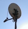
 Took some pictures of LNB-holder and feedarms. When rain stops have plan to catch some signals and tune PM.


.webp")
.webp")
.webp")