Advice Needed Reinforcing Jaeger 1224 EL for Inclined Orbit

moonbase

Small Dish Man
My Satellite Setup
.
My Location
UK
Hi,

Would anyone please be able to provide details of the modification to a Jaeger 1224 EL motor where it is reinforced for inclined orbit tracking? Its the strengthening of the case I am referring to, not the fitting of the shipped brackets that enable inclined orbit tracking.

I think the modification involves strengthening of the lower casing cast metal frame so that it is less likely to break at the point where the inclined orbit jack attaches to it. I recall that when the motors were in production one of the German suppliers was offering an upgraded version of the Jaeger 1224 EL that had this modification applied?

As far as I remember it was an internal lower case modification with some steel (possibly angle iron)?

Rgds
moonbase
 
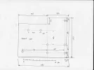
Some German owners attached a "panzer platte" inside wich i also did for a friend .
Rimants is making a extra bottom plate underneat .
 

Attachments

  • panzer platte.webp
    panzer platte.webp
    30.1 KB · Views: 63
  • pantzerplaat.webp
    pantzerplaat.webp
    22.6 KB · Views: 60
Certainly the Angle Iron approach proved most effective for me on my H180 motor ..
Not a 1224 sadly ...but similar in many ways.
rgds
VS
 
How thick does the metal plate need to be 3/4mm or more?
 
How thick does the metal plate need to be 3/4mm or more?
I can't speak for others and indeed other designs ...but I used around 4mm + thick mild steel angle..
 
Some German owners attached a "panzer platte" inside wich i also did for a friend .
Rimants is making a extra bottom plate underneat .

Hi,

Thank you for the picture and the diagram, I think the name is great, "Panzer".

I need to remove the top case cover to have a look inside to see what needs to be removed to get the "Panzer" in the case.
Hopefully not much dismantling required to get the "Panzer" inserted. I need to give the 1224 a clean up and a coat of paint so I will try to fit the "Panzer" then.

Thx for the help
 
Hi,

Any recommendation as to the size of the bolts that should be used and internal diameters of the bolt holes for the plate? Or are they defined by some of the default holes in the bottom of the lower case of the Jaeger 1224 such as where the inclined orbit actuator bracket attaches?

Thx
 
Last edited:
Hi,

I removed the top case cover to see what is going on inside the Jaeger 1224. The 4 x holes in the bottom right corner of the "Panzer" line up perfectly with the 4 x default threaded holes in the lower casing of the 1224 used for fitting the jack bracket for inclined orbit.

It looks like the cylindrical motor needs to be removed to get the "Panzer" into place, the "Panzer" will not slide under the cylindrical motor. The cylindrical motor looks to be secured by two screws to a metal plate with the cogs on the other side. Can anyone please confirm if it is OK to unscrew the two retaining screws and remove the cylindrical motor, I don't want a load of springs and cogs flying everywhere if I take it off ?

Rgds
 
No need to remove that motor in my memory , the plate can be moved under it from the right side .
But even removing is no problem at all , no springs or what so ever .
I used Inox M6 bolts for the plate and M8 to attach the elevation lift-arm wich arm should be longer to the front of the 1224 as the original . (see example , not the real one)
You have to drill some extra holes in the bottom from the 1224 .1224 liftarm.webp
 
Trust1,

Thank you for the picture and the details.
It looks like you have attached your own elevation actuator fixing point to the bottom of the 1224? Was there any reason why you did not use the original brackets to attach the elevation actuator to the 1224?

Could you please provide some details such as dimensions for the elevation actuator brackets that you have made and used and how you fixed them to the 1224?

Many Thx
 
The original elevation actuator fixing point is OK for the original treaded rod to make fine adjustments , but with a actuator the elevation changes to abrupt .
Therefor the attachment point must further away from the elevation axel .
To spread the forces over the bottom from the 1224 , its better to use a to the front also longer rectangular iron . ( I did it not at my first reinforcement , pic 1)
Skystar did his reinforcing on his way , very strong !!
skystar.webp
 

Attachments

  • Afb0022.webp
    Afb0022.webp
    114.6 KB · Views: 37
  • Afb0023.webp
    Afb0023.webp
    87.8 KB · Views: 39
Trust1,

Many thanks for the pictures, it is clearer for me now.

I notice that one of the pictures shows the original large elevation screw threaded bolt still in the 1224 but with the nuts and washers released. Is this kept in place during operation with the inclined orbit actuator, possibly for stability to keep things in alignment?

I have an optical actuator for the elevation adjustment and I think there are a lot more pulse counts per degree compared to a non optical actuator. Is the inclined orbit actuator that you used an optical one or a normal one? I am just thinking if I should get the actuator fixing point away from the body of the motor like you have done if I am using the optical actuator with high pulse counts per degree.
 
Trust1,

Many thanks for the pictures, it is clearer for me now.

I notice that one of the pictures shows the original large elevation screw threaded bolt still in the 1224 but with the nuts and washers released. Is this kept in place during operation with the inclined orbit actuator, possibly for stability to keep things in alignment?

That was just at the time i was constructing the actuator attachment .

I have an optical actuator for the elevation adjustment and I think there are a lot more pulse counts per degree compared to a non optical actuator. Is the inclined orbit actuator that you used an optical one or a normal one?

A normal reedswitch type

I am just thinking if I should get the actuator fixing point away from the body of the motor like you have done if I am using the optical actuator with high pulse counts per degree.

It will be more accurate
 
Back
Top