RS232 serial and STBtool

statalite

Member
My Satellite Setup
SF8008
DiSEqC motor with 1m dish
Zone 1 @ 28.2°E
Zone 2 @ 28.2°E
Channel Master 1.0m (to be setup)
Channel Master 1.2m (to be setup)
SMR 1224
My Location
UK Midlands
Hi guys,

I want to write db_eraser.stb to my DrHD D15 in the hope it will clear it out as it's not working at all apart from the spectrum analyser. I wanted to try this before getting someone to look at the electrolytic capacitors.

Connecting a USB stick directly to the STB the STB says there is insufficient space to write the 123 byte eraser file, however is happy to write original and p firmware which are much larger hence having a go with serial.

I have connected the STB to the Windows 7 PC with a serial cable, unknown if this is a null modem cable, just a US patent number printed and belkin the manufacturer. I suspect normal serial as it's male/female with a f/f gender converter to get it connected.
I'm using STB tool ver1.9.3.
The COM1 port is recognised in device manager
With STB tool ver1.9.3 I click COM1 auto detect, it asks to connect the receiver and turn on which I do but the STB is not being recognised.
Am I doing anything wrongly?
How can I get this to work is there alternative firmware uploading software?
 
Last edited:
You need a real null modem cable, with female plugs at both ends. The gender changer doesn't do the required wire crossings.
 
Ah ok, I will purchase a null modem cable then. Thank you.
 
A null-modem cable is easy to make.
It has the connections:
2-3
3-2
5-5
of the 9-pin connectors (DB9).

So compared to a 'normal' RS232 cable, the pins 2 and 3 are crossed.

So, maybe you can alter the cable you already have?

Greetz,
A33
 
I actually had one but didn't realise so trying it now.
 
Well I'm writing the original firmware to the box just for a test, it's been on 1% for half hour, I know serial is slow but surely it should be more by now?
File size is 2.81 MB.
I don't want to press cancel unless it screws up but 1% does seem slow.
 
Update after 1 hour on 1% I cancelled the process. Box is loading the previous firmware as if I had not tried to overwrite it. More testing tomorrow.
 
Well powered up the box this morning, unfortunately none of this has worked.

As before the box will show signal on a random transponder (no other tp's) the picture would break up and would go completely if you go into the menu or change channel, that sounds like bad circuit or capacitors. I feel I have tried everything software wise.
 
Get the lid off and show us some shots :)

Also was the baud rate set correctly on the PC and did you use a USB To serial or a True serial card?
 
The baud rate was the default at 9600, using the motherboard onboard serial and a null modem cable.
The db_eraser.stb worked fine. I can tell it had by the changes to the channel list.
I will have to get it open and take some pictures.
 
The baud rate was the default at 9600, using the motherboard onboard serial and a null modem cable.
The db_eraser.stb worked fine. I can tell it had by the changes to the channel list.
I will have to get it open and take some pictures.
Yeah get some pics, might be that the flash has had it, too many bad blocks. If it's not capacitor related you could fit a new flash chip.
 
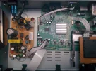
I have opened the box and taken some images, unfortunately I none the wiser, if anyone could see anything?
I may not have taken the images from the best perspective, but none of the caps are bulging.
 

Attachments

  • IMG_20180708_152141_25.webp
    IMG_20180708_152141_25.webp
    99.8 KB · Views: 49
  • IMG_20180708_152207_25.webp
    IMG_20180708_152207_25.webp
    56.6 KB · Views: 48
  • IMG_20180708_152222_25.webp
    IMG_20180708_152222_25.webp
    82 KB · Views: 43
  • IMG_20180708_152234_25.webp
    IMG_20180708_152234_25.webp
    126.8 KB · Views: 39
  • IMG_20180708_153928_25.webp
    IMG_20180708_153928_25.webp
    88.9 KB · Views: 33
I have opened the box and taken some images, unfortunately I none the wiser, if anyone could see anything?
I may not have taken the images from the best perspective, but none of the caps are bulging.
Get the multimeter out and check the outputs on the secondary side of the PSU are correct.
 
Get the multimeter out and check the outputs on the secondary side of the PSU are correct.

I'm an electronics novice with a basic multimeter, what do I need to set the meter to and use the positive and negative on?
 
Warning - during any testing of that PSU, keep your hands well away from the primary side; anything above the chopper transformer T1/capacitor C17/optocoupler PC1 as viewed in your PSU image. Lethal voltages. Normally, this area is delineated by a marked line to show the separation of the primary/secondary areas. Naughty of them to not to make it clear.
 
To my eyes the big capacitor on the PSU is starting to bulge

I took a look at the side profile of this cap and it was really flat so I think it's not bulging however this time around I noticed some solid yellow colour liquid on the circuit board, I assume this capacitor has leaked?

(Not sure if everyone can see on the photo I took)

Could it be "assembly glue"?

Would my PSU work at all if one of the caps was leaking?
 
Last edited:
I took a look at the side profile of this cap and it was really flat so I think it's not bulging however this time around I noticed some solid yellow colour liquid on the circuit board, I assume this capacitor has leaked?

(Not sure if everyone can see on the photo I took)

Could it be "assembly glue"?

Would my PSU work at all if one of the caps was leaking?
PSU caps "Look" fine to me, but if they look good doesn't mean they are good, however if they are domed then they are definitely bad.
There are other bits of the circuit that will provide different voltages, the main thing is to see if all the voltages are present or are not too low/high.
Look at the ribbon cable on the PSU that is going to the board, hopefully they have silkscreened the voltages on there, hard to see in the pics.

Put the multimeter on to Voltage mode and keep one probe on the negative and put the other lead on the other terminals on that ribbon one by one and check, write these down.

If you don't get far in any of this i'd be happy to take a look at the box for you and repair the PSU or swap nand flash/eeprom if possible.

Solid yellow is usually glue they use to stop the cap moving or resonating.
 
PSU caps "Look" fine to me, but if they look good doesn't mean they are good, however if they are domed then they are definitely bad.
There are other bits of the circuit that will provide different voltages, the main thing is to see if all the voltages are present or are not too low/high.
Look at the ribbon cable on the PSU that is going to the board, hopefully they have silkscreened the voltages on there, hard to see in the pics.

Put the multimeter on to Voltage mode and keep one probe on the negative and put the other lead on the other terminals on that ribbon one by one and check, write these down.

If you don't get far in any of this i'd be happy to take a look at the box for you and repair the PSU or swap nand flash/eeprom if possible.

Solid yellow is usually glue they use to stop the cap moving or resonating.

Very kind offer thank you, I will take a look as per your advice and report back.
 
Back
Top