Advice Needed Technics st-gt650 fm tuning issue

Captain Jack

Retired human
My Satellite Setup
See signature
My Location
North Somerset
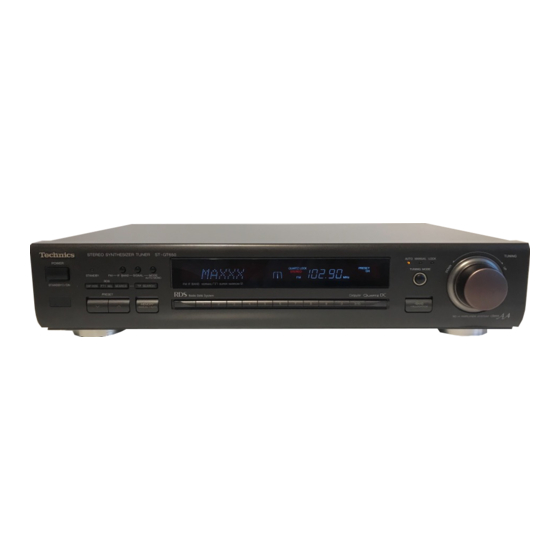
I recently acquired the above-mentioned radio tuner and I am having a small but annoying issue with it. It will not auto-find or lock FM stations, decode RDS or give me stereo sound.

The signal strength is good and audio is nice and clear (but in mono). AM band works OK - it locks onto stations when using automatic search.

I took a quick look around the main PCB and it looks clean with no cracked joints. There is a service manual floating around but I don't want to start replacing various components nilly-willy on the FM side in hope that one of them will resolve the issue. Sadly, no oscilloscope to start probing around.

Any ideas?
 
FM Mode selector button fault/disconnected ?
 
Well... no. As FM signals come in loud and clear, just not locking on properly or decoding RDS.

I suspect either an issue with MPX filter circuit or somewhere before, like the discriminator not set to zero properly.
 
Welp, the discriminator was the culprit. Instead of reading 0mV, it was reading 1.4V! I am hoping that it's the dirty pot and not some other component that has caused to be so far out.
 
@Captain Jack

I have a Technics ST-G70L tuner, which, checking the schematic Terry points to, appears to have similar FM/AM circuitry (without RDS).

I had a problem that seemed to be something like yours, with stereo going down completely some time after the stereo indicator started flickering on and off.
Before checking voltages around the IF Amp/Detector IC102, I tweaked the offset voltage adjustment coil off the IC T101 a little, which restored the stereo O/P. I didn't actually check voltages afterwards - if it happens again I will do so.

The problem occurred after several years' use of the tuner, which leads me to think it may have been due to premature ageing of some components, as the tuner sat above an amp.

The tuner is very well designed, with ample space inside betweem the (linear) PS and main circuit board. I suppose I was unlucky with positioning the tuner immediately above the amp. OK now anyway.
 
Ouch. I can buy an actual oscilloscope for that!
Yah I know, I had a really nice HP scope, the main CPU went FUBAR and they (HP) wanted 3K to fix it, I sold it as non working for 400$ on fleabay, cant afford a new one these days.
 
Welp, the discriminator was the culprit. Instead of reading 0mV, it was reading 1.4V! I am hoping that it's the dirty pot and not some other component that has caused to be so far out.
Hi Jack.
I have the same tuner and when I tune to 97.00Fm which is Heart Plymouth I get sound but no RDS info but if I tune up to 97.05 then I get Heart in the display but no Stereo light lit just mono I have a digital test meter how to you go about the procedure as I can do the job and I've got the service manual.

Thanks
Darryl
 
1608801553694.webp

Connect TP101 and 102 to your multimeter - it should ideally read 0mv. If not, then adjust T101 pot until it does.
 
View attachment 133688

Connect TP101 and 102 to your multimeter - it should ideally read 0mv. If not, then adjust T101 pot until it does.
I have done that I set to 97.00fm heart plymouth then I bought it down to 0v but if I turn the tune dial the voltage varies then.
Plus I broke the core in the discriminator canister but radio is receiver as it should now and not .05mhz out of range.
Can a replacement core be screwed into place Jack?
 
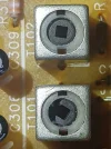
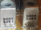
I have managed to get the voltage reduced to practically 0v on a 2v scale on my digital test meter which has solved the .05mhz offset of my frequency display so now I have Heart plymouth on 97.00 instead of 97.05mhz but accidentally cracked the dam ferrite core in the discriminator canister.
Can I replace the ferrite slug screw with one that will fit and still keep the tuning can operable.
 
Regarding the cracked slug, I'd be tempted to leave it where it is because it is now working correctly - but any replacement might be made of another type of ferrite with different permeability, and so might/might not work.
 
If I can find a replacement canister what sort is it I mean is it just a plain variable inductor coil etc etc
 
A few screen shots of my damage.
I guess I should have used the correct tool and last night I thought why the dam didn't I use a matchstick to try and not a jewelry Phillip's Screwdriver
 

Attachments

  • 20201224_000318_001.webp
    20201224_000318_001.webp
    410.5 KB · Views: 8
  • 20201223_233959.webp
    20201223_233959.webp
    323.6 KB · Views: 5
  • 20201223_233933.webp
    20201223_233933.webp
    358.9 KB · Views: 4
  • 20201223_233959.webp
    20201223_233959.webp
    323.6 KB · Views: 4
Technics used to have a service centre on the south coast so you could send it to them (in the New Year)

The parts list should be in the service manual
 
If I could get one I would do it myself as I can repair electronic stuff this was caused by my own stupidity really
I managed to get it to 0v but just had to try and give it a final disaster tweak where I should have stopped while I was winning
 
I was on the idea that ferrite is ferrite and just replace the core screw considering it only screws through a coil
 
Is the voltage on the discriminator surpose to wander a bit in between stations
 
Back
Top