Ka lnb ?

Very good,
For future reference, could you please take a pic of all the units end view, the two coax plug entries, along with the frequency coverage label and also which is the FSS-L or BSS-L type. Thanks.

:)
 
first Ka test with an AN8004 on 16°E :)

Ka 1.webp

I can't put the correct LO on my satfinder.
I tested with data from 28°E with many different transponders and SRs.
After finding some channels I was able to calculate how to directly enter the right frequency with the LO of an universal LNB

Ka 2.webp
 
Yes, the lower part is the TX LO and up-converter and the upper part the driver stages


As John said, it is probably recoverable.

This one was fine after drying and careful cleaning. There was some track erosion around the 2nd LNA bias area but it was easily repaired. The TX board was also usable once cleaned.

View attachment 142002
And yes after a good cleaning the LNB worked fine today :)
So I have two working AN8004 now...
 
first Ka test with an AN8004 on 16°E :)

View attachment 142437

I can't put the correct LO on my satfinder.
I tested with data from 28°E with many different transponders and SRs.
After finding some channels I was able to calculate how to directly enter the right frequency with the LO of an universal LNB

View attachment 142438

Great to see its working , I wonder , maybe it give you more signal when the feedhorn is more close to the dish .
I know difficult to do with that CM lnb holder .
Since I want to do the same test , also with a 1.2 CM , I’m planning to make a wave guide part , 40 mm OD between feedhorn and OMT .
 
Great to see its working , I wonder , maybe it give you more signal when the feedhorn is more close to the dish .
I know difficult to do with that CM lnb holder .
Since I want to do the same test , also with a 1.2 CM , I’m planning to make a wave guide part , 40 mm OD between feedhorn and OMT .
Thank you very much @Trust t for your work on the lnb support, it's great. :-clap
I think we will do the same tests this weekend. :)
I'm also thinking about a solution to make the assembly waterproof and make the support compatible with standard 40mm flanges.
 
I think the idea with the 40mm spacer is very good. You could then attach a plastic tube to it, which is closed at the back. Lead the LNB output to the outside and everything is tight.
 
I think the idea with the 40mm spacer is very good. You could then attach a plastic tube to it, which is closed at the back. Lead the LNB output to the outside and everything is tight.
I do have some ideas about that
 
I would take aluminum tube and glue it into the 40mm adapter. This has the advantage that the surface is smooth and polished on the inside.
 
I would take aluminum tube and glue it into the 40mm adapter. This has the advantage that the surface is smooth and polished on the inside.
I am gonna drill out a spare polarizer and put such alu tube in , having the correct flanges
 
Today I made the "Gilat Longneck" and did some tests with a 1.2 CM at 7º E with my Clarke-tech 5000-C+
With the AN8004 at the original OMT RX port
21.633 H 9.5 dB 21.638 H 12.1 dB
at the TX port 7.9 dB / 10.4 dB
The AN 8002 is stil original and not tested
As you can see the feedhorn is far more close the dish for max signal .

IMG_0717.webp
 
Today I made the "Gilat Longneck" and did some tests with a 1.2 CM at 7º E with my Clarke-tech 5000-C+
With the AN8004 at the original OMT RX port
21.633 H 9.5 dB 21.638 H 12.1 dB
at the TX port 7.9 dB / 10.4 dB
The AN 8002 is stil original and not tested
As you can see the feedhorn is far more close the dish for max signal .

View attachment 142483

Excellent - as usual :Y. Iv'e not tried that method of using the modded omt before , iv'e always gone straight in onto the pcb board with a wr42 adapter with the hope of getting less insertion loss - if i can find another 8004 board and omt i would like to use the same construction method for some performance comparisons.
 
Today I made the "Gilat Longneck" and did some tests with a 1.2 CM at 7º E with my Clarke-tech 5000-C+
With the AN8004 at the original OMT RX port
21.633 H 9.5 dB 21.638 H 12.1 dB
at the TX port 7.9 dB / 10.4 dB
The AN 8002 is stil original and not tested
As you can see the feedhorn is far more close the dish for max signal .

View attachment 142483
the hole on the TX side is smaller than on the RX side.
The transmissions being carried out at higher frequencies this seems normal, right?
Did you modify the hole?

Waveguide.webp
 
No I did not mod the ports (yet)
I called that side port TX port but thats wrong , that port is orignaly closed by a plate .
The TX signal is fed-in through the back of the OMT , that port is 7 x 3 mm .
Both other ports , deep in the wave-guide , are the same , 8 x 2.5mm .
The RX port is going over into 11 x 4.5 mm .
Today I placed the 27.000 Xtal in the AN 8002 and made a blindscan with the LOF 18.250
Found EquTV 19.735 at H and V with 7.9 dB , seems the lnb is in circ mode ( no poplarizer attached)
Maybe caused by the shape of the lnb inlet ? it looks the signal is gonna twisted to the antenna probe .
Since I ruined the first AN 8004 (long time ago) I do have a spare RX body , so I will mod the port to rectangular and see what happens .
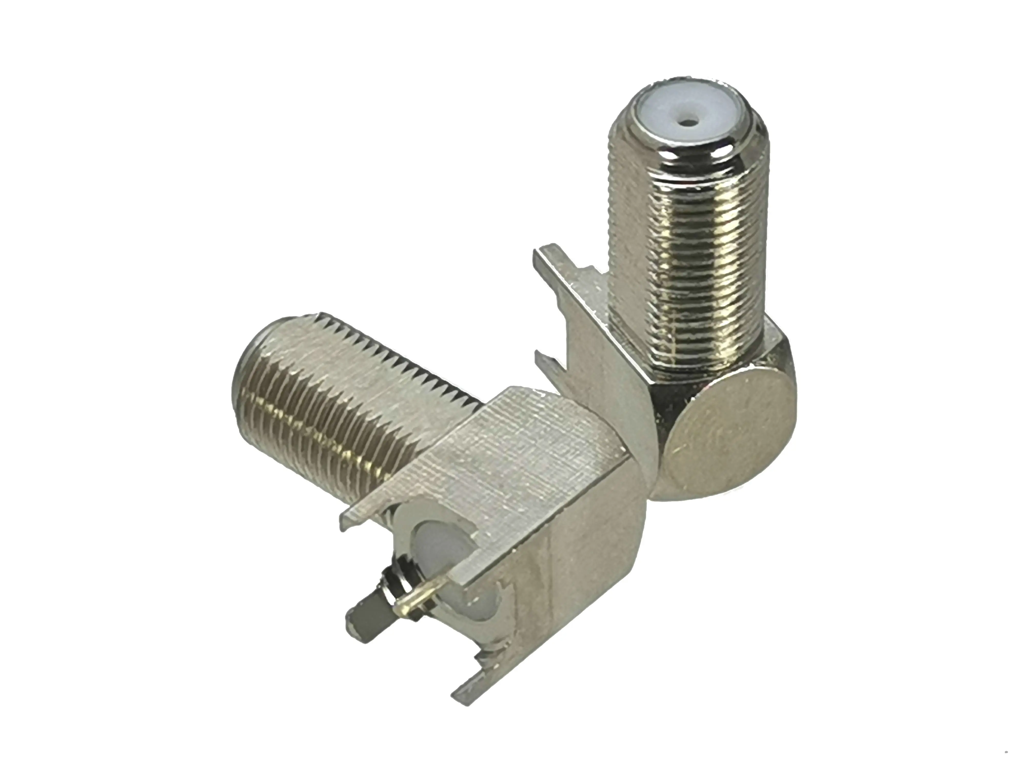
For those people wondering where to get the F connectors , I made them from angled types or from broken moteck rotor boards .
 

Attachments

  • angled F conn.webp
    angled F conn.webp
    183.5 KB · Views: 18
  • twisted inlet inside.webp
    twisted inlet inside.webp
    12.8 KB · Views: 18
  • twisted inlet.webp
    twisted inlet.webp
    11.5 KB · Views: 16
Hello Trust,

I don't want to take away your hope, but I've been experimenting with this constellation for almost a whole year. I have never reached the performance of LNBs individually mounted on OMT port. It was missing up to 3 dB. I really tried everything. If you got better results I would be happy. However, you should always carry out the test with the individual LNB on the OMT.

It works, but there are deviations in performance compared to the individual LNB.

I wish you success:Y
 
Maybe caused by the shape of the lnb inlet ? it looks the signal is gonna twisted to the antenna probe
That turns the polarisation through 90 degrees and it remains linear at that point.
18GHz is probably below cut-off for the TX port on the OMT.
 
That turns the polarisation through 90 degrees and it remains linear at that point.
18GHz is probably below cut-off for the TX port on the OMT.
Effective cutoff of a WR28 transmit port is in the region of 20GHz so some will get through at the upper Ka receive frequencies.
 
Found EquTV 19.735 at H and V with 7.9 dB , seems the lnb is in circ mode ( no poplarizer attached)
More logic , its a single polarity lnb , scanned with13 and 18 V :-doh
After using the OCR setting in the lnb menu , EquTV was found at 18.767

@ Dreamsat , dont worry , I do have fine Ka signal from my 1.8 CM with the SL3K for band A and the KaKua for band D .
Its nice weather to sit on a chair near that 1.2 CM with a big screen in the shade to test .
 
Still with the modded 8002 at 19.2º E , I turned the lnb 90º for V and started a blindscan .
Then I went to the front of the house to wash my car (and wifes car also)
When I came back there was stored a new TP as 17.016 H 3629 .
Unfortunality the signal was gone , so no chance to read the data .
Where did that come from ??
 
Back
Top