Make Gregorian dish

RimaNTSS

Super Moderator
Staff member
Joined
Jan 7, 2009
Messages
5,605
Reaction score
6,080
Points
113
Age
58
My Satellite Setup
Some SAT-related hardware.
My Location
N-E from Riga
OK, will accelerate process little bit: lets put together (on drawings only by now ;) )
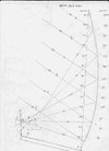
Apply tilt to your LNB 22,6*, as this angle will ensure your system best X-pol characteristics (want to know about this more, look Mizugutch feed axis tilt or Mizugutch condition). Place LNB in such way it does not obstruct signals (green lines on my drawing). Now you can clearly see dots "a" and "b" where green lines crossing red lines (representing illumination angle of LN:cool:. Move LNB left-right and up-down to find proper position of F2 to get distances F1:a + F2:a= F1:b + F2:b. Than draw an ellipse from F1 and F2. ScreenHunter_66 Oct. 13 20.47.jpg
 

RimaNTSS

Super Moderator
Staff member
Joined
Jan 7, 2009
Messages
5,605
Reaction score
6,080
Points
113
Age
58
My Satellite Setup
Some SAT-related hardware.
My Location
N-E from Riga
OK, after drawing of ellipse you will be able to to measure any distances, such as:
- vertical size of SUB- 242 mm;
- distance from point A (very top of antenna) to b (bottom point of SU:cool: - 1420 mm;
- distance from point B (bottom of antenna) to a (top point of SU:cool: - 873 mm;
- distance between F1 and F2 - 72 mm;
- Size of big axe of ellipse - 366 mm;
- angle of leaning of SUB 58,87*
ScreenHunter_67 Oct. 13 21.02.jpg
You can also measure depth of SUB, but, in reality, you do not really need this measurement.
 

RimaNTSS

Super Moderator
Staff member
Joined
Jan 7, 2009
Messages
5,605
Reaction score
6,080
Points
113
Age
58
My Satellite Setup
Some SAT-related hardware.
My Location
N-E from Riga
And if you look at your drawing from far away, you can see that position of feedarm will be little bit different and also longer. Instead of original (~700 mm, red) the new one should longer than 800 mm (green)
ScreenHunter_69 Oct. 13 21.20.jpg
 

skomedal

Regular Member
Joined
Feb 4, 2008
Messages
2,108
Reaction score
2,112
Points
113
My Satellite Setup
This and that
My Location
thule
Am blinded by science:(

Theory is one thing but how do you put into practice ( are you actively constructing a working reflector or relying on others to do it for this project? ).

Just curious as am following this thread along with others.

Regards
 

Riverblue

Regular Member
Joined
Jul 25, 2012
Messages
598
Reaction score
419
Points
63
Age
62
My Satellite Setup
See Signature
My Location
Near Brighton
:-applause I am going to have to have a good "google" and a lot of reading to fully understand and appreciate the progression from post#61 to post#63. :confused This might take a while,
so in the words of Captain Oates "I am just going outside and may be some time" . . . . . . . . But, to quote General MacArthur "I shall return" ;)
 

Riverblue

Regular Member
Joined
Jul 25, 2012
Messages
598
Reaction score
419
Points
63
Age
62
My Satellite Setup
See Signature
My Location
Near Brighton
I found a decent diagram of how a transmission beam is reflected on a gregorian setup


Untitled.png

That'll be "mizuguchi condition"
 

Riverblue

Regular Member
Joined
Jul 25, 2012
Messages
598
Reaction score
419
Points
63
Age
62
My Satellite Setup
See Signature
My Location
Near Brighton
Okay, getting a bit clearer. Just to clarify I'm getting this right
post#62 . . . The line b → F1 → A is the line from the top of a 1.2cm CM dish to the bottom of the sub = 1211mm (parabola 4 measurement) + 208mm (b → F1)

The line a → F1 → B is the line from the bottom of a 1.2cm CM dish to the top of the sub = 712mm (parabola 4 measurement) + 161mm (a → F1)

The lnb is set at 22.6⁰ because that's the offset of the dish.

Wasn't the "phase angle" of the IBU 84⁰, so why are we using 82⁰, is there a reason?

How did you get your measurements in the diagram, did you draw it to scale 1:1 and just measure them off of the drawing, or did you use mathematics?

The leaning angle of the sub is the angle at point b between the red and the blue line?

The depth of the sub is the distance between the blue line and the edge of the ellipse at it's deepest?

F1 → a + F2 → a = F1 → b + F2 → b, 161mm + ? = 208mm + ?, what are the dimensions F2 → a & F1 → b?

Sorry if I'm asking too many questions, I just want to make sure that I'm understanding this correctly ;)
 

RimaNTSS

Super Moderator
Staff member
Joined
Jan 7, 2009
Messages
5,605
Reaction score
6,080
Points
113
Age
58
My Satellite Setup
Some SAT-related hardware.
My Location
N-E from Riga
post#62 . . . The line b → F1 → A is the line from the top of a 1.2cm CM dish to the bottom of the sub = 1211mm (parabola 4 measurement) + 208mm (b → F1)

The line a → F1 → B is the line from the bottom of a 1.2cm CM dish to the top of the sub = 712mm (parabola 4 measurement) + 161mm (a → F1)
Exactely like this, only A-F1 (calculated was not 1211 but 1212 mm.
Wasn't the "phase angle" of the IBU 84⁰, so why are we using 82⁰, is there a reason?
My mistake (perhaps misled from post 41). Should be 84*. Now you can redraw everything and see how 2* change the picture.
How did you get your measurements in the diagram, did you draw it to scale 1:1 and just measure them off of the drawing, or did you use mathematics?
Made it in scale 1:1 and then measured.
The leaning angle of the sub is the angle at point b between the red and the blue line?
No, it is between horizontal line and blue line.
The depth of the sub is the distance between the blue line and the edge of the ellipse at it's deepest?
As I've said before, you do not really need this parameter, and moreover it is not so easy to find deepest point as curve quiet flat.

F1 → a + F2 → a = F1 → b + F2 → b, 161mm + ? = 208mm + ?, what are the dimensions F2 → a & F1 → b?
F2→a = 205, and F2→b = 158
 

RimaNTSS

Super Moderator
Staff member
Joined
Jan 7, 2009
Messages
5,605
Reaction score
6,080
Points
113
Age
58
My Satellite Setup
Some SAT-related hardware.
My Location
N-E from Riga
Theory is one thing but how do you put into practice ( are you actively constructing a working reflector or relying on others to do it for this project? ).
Practice without theory is not really proper way to do things. When we finish with theory, surely we can discuss way ahead towards DIY SUB. In our life we not always can relay on ourselves, one is good, many of us is better.
 

Riverblue

Regular Member
Joined
Jul 25, 2012
Messages
598
Reaction score
419
Points
63
Age
62
My Satellite Setup
See Signature
My Location
Near Brighton
No, it is between horizontal line and blue line.
So it is the angle at point a, between the line F1 → a and the blue line?
 

Riverblue

Regular Member
Joined
Jul 25, 2012
Messages
598
Reaction score
419
Points
63
Age
62
My Satellite Setup
See Signature
My Location
Near Brighton
The depth of the sub is the distance between the blue line and the edge of the ellipse at it's deepest?
As I've said before, you do not really need this parameter, and moreover it is not so easy to find deepest point as curve quiet flat.
Okay, but am I right? I am just asking so that I can make sure that I am understanding every aspect of this.
 

RimaNTSS

Super Moderator
Staff member
Joined
Jan 7, 2009
Messages
5,605
Reaction score
6,080
Points
113
Age
58
My Satellite Setup
Some SAT-related hardware.
My Location
N-E from Riga

Riverblue

Regular Member
Joined
Jul 25, 2012
Messages
598
Reaction score
419
Points
63
Age
62
My Satellite Setup
See Signature
My Location
Near Brighton
OK, you are right! That did not let you sleep this night? :-rofl2
No problem sleeping my friend, just logged on quickly after I'd come back from a night out, definitely no alcohol involved! ;)

Enjoy the fishing! :D
 

Riverblue

Regular Member
Joined
Jul 25, 2012
Messages
598
Reaction score
419
Points
63
Age
62
My Satellite Setup
See Signature
My Location
Near Brighton
How was the fishing Rima?Did you catch anything decent?:)

One quick question, how do you calculate the width of the sub? Or is it circular?

So now I know a lot more about how a gregorian set up works and have a reasonable understanding of how to calculate the positions/sizes of the main components of the design. What would be the next step, discussing possible designs?
If we are still basing this on a Channel Master dish then the main thing is surely how to redesign the lnb support arms to enable them to support the sub in it's correct position and an arrangement to hold the lnb in the correct position as well. Ideally I think it would be a good idea if both of these positions were some how adjustable to enable the inevitable tinkering and fine tuning that I feel a home grown design would probably need. Ideas, discuss? :D
 

RimaNTSS

Super Moderator
Staff member
Joined
Jan 7, 2009
Messages
5,605
Reaction score
6,080
Points
113
Age
58
My Satellite Setup
Some SAT-related hardware.
My Location
N-E from Riga
Fishing was just great, had lots of fun and also caught lots of flatfish (I got ~40 of them).
No need to calculate width of SUB, that will net be circular but oval. Vertical size of SB is always slightly bigger than horizontal.
For feedarm for my 1,8m Prodelin I went universal way. This is support for LNB, adjustable in all directions. Something similar could be made for SUB as well. P1430293 (Large).JPG
What would be the next step, discussing possible designs?
Perhaps it is little bit too early (however I have some ideas about that). But, there is at least one, unsolved theoretical issue, to be precise that is tilting of LNB.... or Mizugutch condition. When I made drawings I made this tilt 22,6*, as offset angle of antenna, but in reality this tilting angle should be different. Appreciate if somebody could explain everything about this condition. This is very important for X-pol issues of Gregorian antenna.
 

Riverblue

Regular Member
Joined
Jul 25, 2012
Messages
598
Reaction score
419
Points
63
Age
62
My Satellite Setup
See Signature
My Location
Near Brighton
I'll be truthfull, I've read numerous articles about the "Mitzuguchi Condition" and I couldn't even begin to try and explain what it's all about!

I was thinking along the same lines, I remembered this from one of your threads!


Untitled.png
 

Trust

Specialist Contributor
Joined
Jul 18, 2004
Messages
1,133
Reaction score
1,618
Points
113
Age
77
My Satellite Setup
1.8 m CM at SMR 1224 + Elev. with 7 lnb changer Ku (lin - circ) - Ka (lin - circ) C (lin - circ)
My Location
Nijmegen Netherlands
I found a decent diagram of how a transmission beam is reflected on a gregorian setup


View attachment 69221

That'll be "mizuguchi condition"
This picture is not showing how the reflection at a Fibo 120 is , the subrefl. is more tilted forward and the lnb is between main reflc. and sub .
I once messured my dish carefully and made a drawing with incoming and reflected signal lines .
Dish was optimal pointed at 4.8º E with elevation of 30.7º for my location .
Frontline of the main reflector leans back 3º so calculated offset angle 30.7 - 3 = 27.7º
 

Attachments

  • focus lijnen.jpg
    focus lijnen.jpg
    49.4 KB · Views: 58
Last edited:

RimaNTSS

Super Moderator
Staff member
Joined
Jan 7, 2009
Messages
5,605
Reaction score
6,080
Points
113
Age
58
My Satellite Setup
Some SAT-related hardware.
My Location
N-E from Riga
If you download ICARA product "Single or Dual Reflector Design" and get familiar with it's interface, than t can probably help to know more about X-pol reduction and other Gregorian type antenna parameters.
ScreenHunter_75 Oct. 27 21.34.jpg
 

RimaNTSS

Super Moderator
Staff member
Joined
Jan 7, 2009
Messages
5,605
Reaction score
6,080
Points
113
Age
58
My Satellite Setup
Some SAT-related hardware.
My Location
N-E from Riga

Riverblue

Regular Member
Joined
Jul 25, 2012
Messages
598
Reaction score
419
Points
63
Age
62
My Satellite Setup
See Signature
My Location
Near Brighton
I've not been around for a while, are we not going anywhere with this?
Sorry, but still not really getting this Mitzuguchi condition. Can anyone put this in simpler terms?
 
Top