You are using an out of date browser. It may not display this or other websites correctly.
You should upgrade or use an alternative browser.
You should upgrade or use an alternative browser.
Captain Jack
Burnt out human
- Joined
- Oct 21, 2006
- Messages
- 11,806
- Reaction score
- 7,990
- Points
- 113
- My Satellite Setup
- See signature
- My Location
- North Somerset
Thought I'd take a look at this again having had the parts since 2016 but not really fitted it properly. I also have @dreambox1959's positioner, which can drive the LNB changer directly.
The dish is the Channel Master 1.8m and I'd like to see from others who fitted it (@stephan94 @cardiff) whether any of my original measurements that I received from @Trust are still valid or whether some tweaks are required.
Here's the original diagram that I have (click on picture):
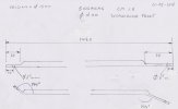
And the result from the above.
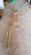
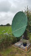
I seem to remember that it wasn't quite the same signal quality as the original arms, hence the question.
The dish is the Channel Master 1.8m and I'd like to see from others who fitted it (@stephan94 @cardiff) whether any of my original measurements that I received from @Trust are still valid or whether some tweaks are required.
Here's the original diagram that I have (click on picture):

And the result from the above.


I seem to remember that it wasn't quite the same signal quality as the original arms, hence the question.
cardiff
Regular Member
- Joined
- Mar 1, 2006
- Messages
- 79
- Reaction score
- 69
- Points
- 18
- Age
- 61
- Location
- Brittany
- My Satellite Setup
- Laminas As 1800, multifocus 14 LNB
- My Location
- France
On my laminas 1800 with the Lnb Changer (which are completely dismantled)
the original arms are used and the central arm was designed by Trust,
he used at the time a laminas 1800 from another person for the adaptation for the Lnb Changer
I do not have Channel Master 1.8m
Cardiff
the original arms are used and the central arm was designed by Trust,
he used at the time a laminas 1800 from another person for the adaptation for the Lnb Changer
I do not have Channel Master 1.8m
Cardiff
Captain Jack
Burnt out human
- Joined
- Oct 21, 2006
- Messages
- 11,806
- Reaction score
- 7,990
- Points
- 113
- My Satellite Setup
- See signature
- My Location
- North Somerset
Ah right, my mistake - I assumed it was the CM one.
John
Enthusiast.
- Joined
- Jan 1, 2000
- Messages
- 3,735
- Reaction score
- 5,541
- Points
- 113
- Location
- North Nottinghamshire.
- My Satellite Setup
-
Elite 2.2 PF - CM1.8 - CM1.2 - Gibertini 1.25.
Ku - Ka -C & Ext C.
PC cards-TM5402 receivers.
Promax FSM.
- My Location
- North Nottinghamshire.
Thought I'd take a look at this again having had the parts since 2016 but not really fitted it properly. I also have @dreambox1959's positioner, which can drive the LNB changer directly.
The dish is the Channel Master 1.8m and I'd like to see from others who fitted it (@stephan94 @cardiff) whether any of my original measurements that I received from @Trust are still valid or whether some tweaks are required.
Here's the original diagram that I have (click on picture):
View attachment 138082
And the result from the above.
View attachment 138083View attachment 138084
I seem to remember that it wasn't quite the same signal quality as the original arms, hence the question
Don't know if it's an optical delusion CJ but the lnb itself looks too high and looks as if the motor should be 'hanging' from the centre box section for correct lnb positioning and might be the cause of the lower signal strengths you mentioned. I'll dig back into my records and pictures of when i altered my lnb positioning on my 1.8CM to Rima's suggested position. I also made a wooden 'template' constructed to Rima's angle measurements etc which assists lnb alignment greatly. Bare with me and i'll show some pics
 .
.John
Enthusiast.
- Joined
- Jan 1, 2000
- Messages
- 3,735
- Reaction score
- 5,541
- Points
- 113
- Location
- North Nottinghamshire.
- My Satellite Setup
-
Elite 2.2 PF - CM1.8 - CM1.2 - Gibertini 1.25.
Ku - Ka -C & Ext C.
PC cards-TM5402 receivers.
Promax FSM.
- My Location
- North Nottinghamshire.
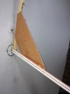
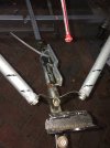
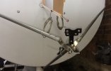
This is what i did for lnb alignment on my CM 1.8 Test Rig CJ if it's any use to you.
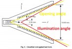
I adopted Rimants suggested lnb position angles which are in a thread on the forum - I did an illumination test using the original CM feed with revolving lazer pen at lnb using the original CM side arms and lower arm position and original lnb holder. Long story short, original CM illumination gave over illumination at the bottom of the dish by a fair amount collecting unwanted ground noise, and under illumination of the dish at the top, robbing me of signal - there's one of my forum threads buried somewhere which shows a video of the illumination test some where.
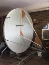
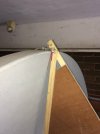
The wooden template is constructed to Rimants dimensions and knocked up out of 25mm x 5mm pine strips with a couple of plywood strengthening gussets etc glued into place. After careful positioning of the template to make sure the red tip at the end of the template is equal distance left and right of dish edges etc another illumination test was done which gave a perfect illumination tracking all around the dish edge - reception results afterwards showed an improvement over the original CM set up.
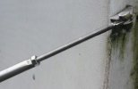
The bracketry at lnb area shows one of Rimants stainless arm supports but i modified the rest by making custom aux brackets to accept a variety of different lnb types and sizes that enabled the test lnb to be positioned with the red metal tip to be at the focal point and also the right pointing angle to the dish.
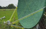
It worked for me CJ - here's a few pics
Note: The side arm positions shown are in a lower fixed position than original - long story short, gives more clearance for different or larger lnb sizes.
..............................................................................................................................................................................................................................................................................................................................


Last edited:
Captain Jack
Burnt out human
- Joined
- Oct 21, 2006
- Messages
- 11,806
- Reaction score
- 7,990
- Points
- 113
- My Satellite Setup
- See signature
- My Location
- North Somerset
Crikey - that's quite a construction! Thanks for that.
I'll need to dig out your other posts for measurements (and pin the threads!)
I'll need to dig out your other posts for measurements (and pin the threads!)
- Joined
- May 26, 2020
- Messages
- 5,204
- Reaction score
- 2,609
- Points
- 113
- My Satellite Setup
- Raven mk2 zone 2 x4, Channel Master: 90cm x3, 1.2m x2, 1.8m PF. CM polar mount x2, Az/El x3.
- My Location
- South Durham
RimaNTSS LNB position measurements for Channel Master dishes:

 www.satellites.co.uk

Help Required - CM 2.4 m dimensions
I have to make a lnb changer for a CM 2.4 m offset dish . Can someone tell me the exact size of the dish , hight , wide and dept ? Also like to that both half parts have the same dimensions .
scopus
Specialist Contributor
- Joined
- Mar 25, 2005
- Messages
- 3,178
- Reaction score
- 3,811
- Points
- 113
- Age
- 59
- My Satellite Setup
- Primesat/Famaval 1.8 PF C/ku/Ka, Octagon SX8HD1, SX88, Openbox S3 Mini HD-V8S Freesat V7 HD-V8 Finder, Amiko A4K Combo, Satlook Colour HD Spectrum, Sansui A909 Amp and BOSE Acoustimass speakers for the audio.
- My Location
- Staffs UK
Probably why a standard 40mm LNB without the pukka feedhorn always worked better...This is what i did for lnb alignment on my CM 1.8 Test Rig CJ if it's any use to you.
I adopted Rimants suggested lnb position angles which are in a thread on the forum - I did an illumination test using the original CM feed with revolving lazer pen at lnb using the original CM side arms and lower arm position and original lnb holder. Long story short, original CM illumination gave over illumination at the bottom of the dish by a fair amount collecting unwanted ground noise, and under illumination of the dish at the top, robbing me of signal - there's one of my forum threads buried somewhere which shows a video of the illumination test some where.
The wooden template is constructed to Rimants dimensions and knocked up out of 25mm x 5mm pine strips with a couple of plywood strengthening gussets etc glued into place. After careful positioning of the template to make sure the red tip at the end of the template is equal distance left and right of dish edges etc another illumination test was done which gave a perfect illumination tracking all around the dish edge - reception results afterwards showed an improvement over the original CM set up.
The bracketry at lnb area shows one of Rimants stainless arm supports but i modified the rest by making custom aux brackets to accept a variety of different lnb types and sizes that enabled the test lnb to be positioned with the red metal tip to be at the focal point and also the right pointing angle to the dish.
It worked for me CJ - here's a few pics
Note: The side arm positions shown are in a lower fixed position than original - long story short, gives more clearance for different or larger lnb sizes.
..............................................................................................................................................................................................................................................................................................................................
View attachment 138095View attachment 138096View attachment 138097View attachment 138098View attachment 138099
- Joined
- Jan 7, 2009
- Messages
- 5,604
- Reaction score
- 6,080
- Points
- 113
- Age
- 58
- My Satellite Setup
- Some SAT-related hardware.
- My Location
- N-E from Riga
@Captain Jack I think you have to make new side-feedarms and also make possible that the bottom-feedarm can be attached at the bottom of the dish to change the length as well. On the attached picture, you can see how I made side-arms adjustable. So, at the end of the day, you will be able to place the feed in such a way that it's phase center is co-located with the antenna's focal point.
Attachments
Captain Jack
Burnt out human
- Joined
- Oct 21, 2006
- Messages
- 11,806
- Reaction score
- 7,990
- Points
- 113
- My Satellite Setup
- See signature
- My Location
- North Somerset
@RimaNTSS - yep the feedarms are not original but made following @Trust's specifications (buried somewhere in my PMs). They are not adjustable though, just fixed. I don't know how far out of spec these arms I made are - hence why I was hunting for more recent measurements of everything.
But I think I'll make the wooden structure like John's and go from there.
But I think I'll make the wooden structure like John's and go from there.
Captain Jack
Burnt out human
- Joined
- Oct 21, 2006
- Messages
- 11,806
- Reaction score
- 7,990
- Points
- 113
- My Satellite Setup
- See signature
- My Location
- North Somerset
- Joined
- Jan 7, 2009
- Messages
- 5,604
- Reaction score
- 6,080
- Points
- 113
- Age
- 58
- My Satellite Setup
- Some SAT-related hardware.
- My Location
- N-E from Riga
Yes, the "P" point is inside the feedhorn. Approximately how you can see on the attached pick.the F point, is that somewhere inside of the LNB, where the probes are or the LNB opening?
Attachments
zorrin
Specialised contributor
- Joined
- Nov 12, 2008
- Messages
- 444
- Reaction score
- 434
- Points
- 63
- Age
- 51
- Location
- France
- Website
- www.facebook.com
- My Satellite Setup
-
CM 1m20 Ku 52°E to 45°O GTMEDIA V9 Prime
CM 1m20 Ku 50°E to 45°O OCTAGON SF8008
- My Location
- france
Hi @cardiffHello everybody,
Some pictures of my new LNB Changer with motor at the back and not at the front, the reception is perfect, everything works fine, missing for now 1 or 2 Av-COMM polarizer with servo motor.
Thank's Trust1 and his golden hands, you help me by answering all my questions for the problems with the old and new LNB Changer for my Laminas dish AS1800. I do not forget to tell the lnb twin GI-212E (Ku band), "probably one of the best".
View attachment 106493
View attachment 106494
Rgds
Cardiff
Admin edit - two dead image libnks removed & pics uploaded to our server.
Can you post more picture of your back solution please ?
cardiff
Regular Member
- Joined
- Mar 1, 2006
- Messages
- 79
- Reaction score
- 69
- Points
- 18
- Age
- 61
- Location
- Brittany
- My Satellite Setup
- Laminas As 1800, multifocus 14 LNB
- My Location
- France
Hello zorrin,
Sorry everything has been disassembled for more than 6 months and since then I have broken several fingers on my right hand and I can't do anything for the moment.
Cardiff
Sorry everything has been disassembled for more than 6 months and since then I have broken several fingers on my right hand and I can't do anything for the moment.
Cardiff
zorrin
Specialised contributor
- Joined
- Nov 12, 2008
- Messages
- 444
- Reaction score
- 434
- Points
- 63
- Age
- 51
- Location
- France
- Website
- www.facebook.com
- My Satellite Setup
-
CM 1m20 Ku 52°E to 45°O GTMEDIA V9 Prime
CM 1m20 Ku 50°E to 45°O OCTAGON SF8008
- My Location
- france
The only solution for you right now is IPTV in your situationHello zorrin,
Sorry everything has been disassembled for more than 6 months and since then I have broken several fingers on my right hand and I can't do anything for the moment.
Cardiff
But you already gave me ideas

dreambox1959
Specialist Contributor
- Joined
- Feb 7, 2009
- Messages
- 419
- Reaction score
- 557
- Points
- 93
- Age
- 64
- Location
- 46.3N-4.3E-FRANCE
- My Satellite Setup
- Octagon SF8008 - technomate 7100
- My Location
- france
hello everyone
i want to know the electricity consumption of an lnb changer made with diseqc1.2 motor .
can someone make intensity measurement with 14V or 18V .
100mA / 500mA/ 1A ????
special offer !!
i find this on an advertisement:
Alimentation 13 / 18 VDC
Consommation
mode standby :50 mA normal :200 mA maxi: 350 mA
Vitesse de rotation 1,9° / sec. (à 13 V); 2,9° / sec. (à 18 V)
is it real ?
Last edited:
femi
Member
- Joined
- Aug 4, 2004
- Messages
- 28
- Reaction score
- 33
- Points
- 13
- Location
- Austria
- My Satellite Setup
- Irte 2.4m (C-Ku-band), Laminas 1.8m (Ka-Ku-C-band), a lot of other small dishes, terrestrical antennas and receivers
- My Location
- Lower Austria
Technirotor
50mA (Standby) / 200mA (Normal) / 350mA (max.)
It's the documentation from Technisat, I think this source is trustworthy.
Also STAB SAT antenna rotor HH 100
Current in stand-by: 30 mA
Working current: 190 mA
Max. Total current: 350 mA
Rotation speed: 1.8°/s(18V) ; 1,2°/s(13V)
50mA (Standby) / 200mA (Normal) / 350mA (max.)
It's the documentation from Technisat, I think this source is trustworthy.
Also STAB SAT antenna rotor HH 100
Current in stand-by: 30 mA
Working current: 190 mA
Max. Total current: 350 mA
Rotation speed: 1.8°/s(18V) ; 1,2°/s(13V)
Last edited:

