Tests of 120cm antennas

Captain Jack

Burnt out human
Joined
Oct 21, 2006
Messages
11,808
Reaction score
7,991
Points
113
My Satellite Setup
See signature
My Location
North Somerset
Interesting. I do wonder what results Rimant's experiments will yield. Some good reading here.
 

RimaNTSS

Super Moderator
Staff member
Joined
Jan 7, 2009
Messages
5,605
Reaction score
6,081
Points
113
Age
58
My Satellite Setup
Some SAT-related hardware.
My Location
N-E from Riga
I will try and finish reading Paul Wade's book first for a better understanding.
When you reading all those books and see somewhere answers to questions we could not answer previously, just let us know:
- How to measure (find out) illumination angle of feedhorn?
- How to measure F/D of feedhorn?
Good luck :rolleyes:
 

battenfan

Regular Member
Joined
Sep 11, 2006
Messages
493
Reaction score
341
Points
63
My Satellite Setup
1.2m pf
My Location
60N 18E
I don't know what equipment one would need but I guess they define illumination angle as where the signal lost 10 dB compared to the aiming point which is close to the theoretical compromise between spillover and illumination.
IMUFIG3.JPG

(Image source)

What I was getting at here... if one imagines a polar plot beam as the one above. To illuminate the dish evenly top and bottom, maybe one needs to aim a little higher than our calculated g-spot. The next image shows the aiming point higher than the projected aperture center.

image600.jpg

(Image source)
 

RimaNTSS

Super Moderator
Staff member
Joined
Jan 7, 2009
Messages
5,605
Reaction score
6,081
Points
113
Age
58
My Satellite Setup
Some SAT-related hardware.
My Location
N-E from Riga
Another thing which puzzles me little bit is on attached picture. Seems this is original feedhorn. As far as I know, phase center of the feedhorn is somewhere where I put green dot. But, if we put usual universal LNB in the same holder, than it can not be reaching green dot. LNB's phase center will be located approximately where I put red dot. lr48y.jpg
 

Riverblue

Regular Member
Joined
Jul 25, 2012
Messages
598
Reaction score
419
Points
63
Age
62
My Satellite Setup
See Signature
My Location
Near Brighton
As far as I know, phase center of the feedhorn is somewhere where I put green dot. But, if we put usual universal LNB in the same holder, than it can not be reaching green dot. LNB's phase center will be located approximately where I put red dot.
Looking at an image of a Channel Master feed horn (I don't have one!) the Scalar rings (correct term?) don't seem to project internally too much. Seeing as the dish has an opening angle of 80º I would expect the feed horn to be designed to suit? Would it not place the phase centre more likely as indicated in my image below and thereby closer to a position obtainable by a universal lnb? If not could you explain why not so that I can improve my understanding Rima :)

14.png

Untitled.png 13.png
 

RimaNTSS

Super Moderator
Staff member
Joined
Jan 7, 2009
Messages
5,605
Reaction score
6,081
Points
113
Age
58
My Satellite Setup
Some SAT-related hardware.
My Location
N-E from Riga
@Riverblue I doubt Phase center of feedhorn can be located where you just pointed. What would you say about this picture I screenshoted some time agoScreenHunter_101 Dec. 05 20.38.jpg ?
 
A

archive10

Guest
Another thing which puzzles me little bit is on attached picture. Seems this is original feedhorn. As far as I know, phase center of the feedhorn is somewhere where I put green dot. But, if we put usual universal LNB in the same holder, than it can not be reaching green dot. LNB's phase center will be located approximately where I put red dot. View attachment 72843
I think this is one of the reasons you get really good results with the Inverto black ultras - they have a very long neck, and the integrated feedhorn (and thuse the phase center) can be pushed very close to where the CM feedhorn has it. At that point me be placed where it is (in relation to the feed holder) to accomodate feedhorns - remember this was designed primarily as a (semi-)pro dish.
See first attached picture for the optimal position on my CM180 (as measured with the ProMax).

In contrast, other designs has the phase center much closer to the holder to support modern universal LNBs with denser feed-horn designs.
See second attached picture for my Wavefrontier T55, where the IBU is held at the other end of the neck.
 

Attachments

  • IMAG0829q.jpg
    IMAG0829q.jpg
    154.3 KB · Views: 75
  • IMAG0831q.jpg
    IMAG0831q.jpg
    80.1 KB · Views: 71

Riverblue

Regular Member
Joined
Jul 25, 2012
Messages
598
Reaction score
419
Points
63
Age
62
My Satellite Setup
See Signature
My Location
Near Brighton
@Riverblue I doubt Phase center of feedhorn can be located where you just pointed. What would you say about this picture I screenshoted some time ago ?

A bit more research and I came across this:

Untitled.png 17.png
This would suggest that the phase centre would be more likely like this:Untitled.png 19.png

This seems to concur more with your post Rima. :)
 

RimaNTSS

Super Moderator
Staff member
Joined
Jan 7, 2009
Messages
5,605
Reaction score
6,081
Points
113
Age
58
My Satellite Setup
Some SAT-related hardware.
My Location
N-E from Riga
Yes, fine, but I still have some concerns.... I measured dish and calculated all the needed dimensions (used several programs) and got focal point of this dish less than 3cm from holder, where I put red dot now :cool:
I start to suspect that there are 2 different types of feedarms available for the same dish: one to be used with original feedhorn and other for universal LNB.
 

Attachments

  • IMG_20150131_161025 (Large).jpg
    IMG_20150131_161025 (Large).jpg
    99.6 KB · Views: 39
A

archive10

Guest
Yes, fine, but I still have some concerns.... I measured dish and calculated all the needed dimensions (used several programs) and got focal point of this dish less than 3cm from holder, where I put red dot now :cool:
I start to suspect that there are 2 different types of feedarms available for the same dish: one to be used with original feedhorn and other for universal LNB.
A reasonable thought.
But after having scrutinised parts list from various incarnations of the CM manufacturer for some time now, I have never come across other single feed-arms for the dishes (100 120 180 and 240). Sure, they have other feed arms configurations, but thoser are the heavy-duty stuff for large Tx/Rx configs, yet *still* use the same feedhorn.
And I have a metal feed-holder (as opposed to the black plastic one you got) specficially made for Rx/Tx ops (e.g. Tooway TV).
This has a keyed flange support that directly matches the CM feedhorn, but uses the same 3 tubular feed-arms.
So I am fairly certain there is only one set of feed-arms available.
Rx/Tx which only fits the CM feedhorn, and that
 

Riverblue

Regular Member
Joined
Jul 25, 2012
Messages
598
Reaction score
419
Points
63
Age
62
My Satellite Setup
See Signature
My Location
Near Brighton
Yes, fine, but I still have some concerns.... I measured dish and calculated all the needed dimensions (used several programs) and got focal point of this dish less than 3cm from holder, where I put red dot now :cool:


A reasonable thought.
But after having scrutinised parts list from various incarnations of the CM manufacturer for some time now, I have never come across other single feed-arms for the dishes (100 120 180 and 240). Sure, they have other feed arms configurations, but thoser are the heavy-duty stuff for large Tx/Rx configs, yet *still* use the same feedhorn.
And I have a metal feed-holder (as opposed to the black plastic one you got) specficially made for Rx/Tx ops (e.g. Tooway TV).
This has a keyed flange support that directly matches the CM feedhorn, but uses the same 3 tubular feed-arms.
So I am fairly certain there is only one set of feed-arms available.
Rx/Tx which only fits the CM feedhorn, and that

This takes me back to my post*56, I find it hard to believe that these dishes have been designed so far away from the ideal!

Rima, is there something that we are missing regarding calculations, focal point etc of this dish? Something that is specific to the reception of a signal with an offset dish? o_O
 

RimaNTSS

Super Moderator
Staff member
Joined
Jan 7, 2009
Messages
5,605
Reaction score
6,081
Points
113
Age
58
My Satellite Setup
Some SAT-related hardware.
My Location
N-E from Riga
is there something that we are missing regarding calculations, focal point etc of this dish? Something that is specific to the reception of a signal with an offset dish?
If I knew I would certainly shoot it out :(
BTW, I wrote to CM asking question about LNB's aiming point. Pending their answer.
What we can do.... perhaps we can do some actions (measurements, discussions, tests... ) IOT agree about CM1,2m dimensions, such as distance from focal point to top and bottom of the dish, LNB's proper aiming point.
 

Trust

Specialist Contributor
Joined
Jul 18, 2004
Messages
1,133
Reaction score
1,618
Points
113
Age
77
My Satellite Setup
1.8 m CM at SMR 1224 + Elev. with 7 lnb changer Ku (lin - circ) - Ka (lin - circ) C (lin - circ)
My Location
Nijmegen Netherlands
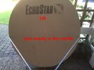
Nono, what I mean with working areas is effectively the area illuminated by the feed-horn, is we had a transmitting LNB attached to it.
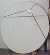
This may be different from the corrugated plastic areas (as in your photo), and also different from the metal mesh/layer embedded in the dish.
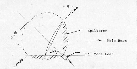
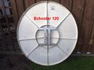
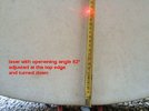
It would be very intersting if we could get @Trust1 to mount his circular-laser device on the CM120, and simulate a 78* feedhorn on the reflector.
I blieve that this would show where the "ideal" working areas is according to the design of the dish.
Well , not a CM but a Echostar , I will arrange the CM later this week .
The aiming-point is exacly in the middle , adjusting the rotating laser at the top edge (making a angle of 62º) and turning , shows its passing the bottomside at 21 cm from the edge .
Adjusted the laser angle to the asked 78º , shows the spot at the bottomside 8 cm from the edge , with turning its leaving the the dish very quick .
 

Attachments

  • Echostar 120 back.jpg
    Echostar 120 back.jpg
    46.9 KB · Views: 61
  • 62º spot down.jpg
    62º spot down.jpg
    49.7 KB · Views: 58
  • middle spot.jpg
    middle spot.jpg
    48.2 KB · Views: 55
Last edited:

RimaNTSS

Super Moderator
Staff member
Joined
Jan 7, 2009
Messages
5,605
Reaction score
6,081
Points
113
Age
58
My Satellite Setup
Some SAT-related hardware.
My Location
N-E from Riga
Thanks @Trust1 ! That just proves that if you point LNB some 10cm ish lower than whole surface of the dish would be illuminated.
 

RimaNTSS

Super Moderator
Staff member
Joined
Jan 7, 2009
Messages
5,605
Reaction score
6,081
Points
113
Age
58
My Satellite Setup
Some SAT-related hardware.
My Location
N-E from Riga
I realise that some things are not made or designed well, but this is a dish that has been made by three different companies in succession for 15 years or so, apparently Skyware Global, the current manufacturers, still use the original Andrews moulds for the SMC dish faces. I find it hard to believe that these dishes have survived being manufactured for this length of time if they have been designed so poorly.
I would like to reiterate on this..... I think that who ever made first mold of this great dish, did not pay lots of attention to quality of their end product. Who ever replicate first design made same mistakes. So on and so on, till we get almost all antennas available on the market produced and sold with same hardware mistake. And basic mistake is - LNB is not pointed to the right spot of antenna (does not matter which program you use for calculations or just common sense). I do not believe antenna's designers intentionally moved aiming point to the center of the dish. So, yes, I am accusing them for mistake they did. I will do some tests soon and if tests show negative results I will take my word back :mad:. I think that performance of systems with CM1,2m dishes can be improved by adjusting LNB's position and direction. That's all folks. :rolleyes:
 

Trust

Specialist Contributor
Joined
Jul 18, 2004
Messages
1,133
Reaction score
1,618
Points
113
Age
77
My Satellite Setup
1.8 m CM at SMR 1224 + Elev. with 7 lnb changer Ku (lin - circ) - Ka (lin - circ) C (lin - circ)
My Location
Nijmegen Netherlands
I asked my friend PaulvR to bring over his stored 120 CM , and he did , so Rima , when I can manage to get the Visiosat Thursday , we can play saturday with both if you want .
Thanks to HvdH , he pointed me to the fact that he gave that dish to Paul .
I also made the adapter for use of your 40 mm aiming-pointer in a 23 mm clamp .
 

RimaNTSS

Super Moderator
Staff member
Joined
Jan 7, 2009
Messages
5,605
Reaction score
6,081
Points
113
Age
58
My Satellite Setup
Some SAT-related hardware.
My Location
N-E from Riga
I see, you already planned my Saturday! :-lol Maybe it is good, I will have some excuse to wife to cancel useless food-shopping day.
23mm adapter.... maybe too optimistic, as they also had made 20mm LNB holders :eek:

Add: And arrange nice weather conditions for Saturday then.
 

Trust

Specialist Contributor
Joined
Jul 18, 2004
Messages
1,133
Reaction score
1,618
Points
113
Age
77
My Satellite Setup
1.8 m CM at SMR 1224 + Elev. with 7 lnb changer Ku (lin - circ) - Ka (lin - circ) C (lin - circ)
My Location
Nijmegen Netherlands
In fact , your wife asked me to keep you out of the way :-biglaugh I forgot to ask what plans she has .
Ok tomorrow I cut the adapter down to 20 mm , with pieces of pvc pipe around it , it can be used for 23 mm
 

RimaNTSS

Super Moderator
Staff member
Joined
Jan 7, 2009
Messages
5,605
Reaction score
6,081
Points
113
Age
58
My Satellite Setup
Some SAT-related hardware.
My Location
N-E from Riga
This is not about 1,2m antenna but about aiming point of LNB. So, mounted feedarms to 1,8m NSC antenna and checked where LNB was pointed when this antenna was used by previous owner. As you can see from attached photo, aiming point was down and little bit right, about 138mm away from calculated aimpoint. This is just for information and to have some food for thought.
Antenna is upside-down to be able to put car in the garage (that box is called GARAGE) :eek:
 

Attachments

  • NSC180 (Large).jpg
    NSC180 (Large).jpg
    31.8 KB · Views: 43

John

Enthusiast.
Joined
Jan 1, 2000
Messages
3,751
Reaction score
5,562
Points
113
Location
North Nottinghamshire.
My Satellite Setup
Elite 2.2 PF - CM1.8 - CM1.2 - Gibertini 1.25.
Ku - Ka -C & Ext C.
PC cards-TM5402 receivers.
Promax FSM.
My Location
North Nottinghamshire.
... just to add to this discussion a bit, i was planning to remove the standard lnb holder on my 120cm CM and fit something different to suit a Ka band set-up. Before i removed it i decided to make a note, drawings, angles etc to where exactly it was located.
This also turned out to be lower than expected, as indicated by the cross on the dish face.
 
Top